| June 11, 2024 | |||||||||||||||||||||||||||||||||||||||||||||||||||||||||||||||||||||||||||||||||||||||||||||||||||||||||||||||||||||||||||||
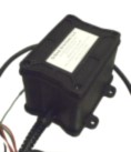
 Small, self-contained automotive battery backup system with 1.2 AH battery. It is a 12 volt DC UPS module or battery backup (BBU) keeps 12 volt equipment alive in cars, trucks and taxis using an internal sealed lead acid battery. Complete battery backup for 12V equipment in buses, cars and other vehicles with 1.2AH battery |
 More battery backups for buses, emergency vehicles and vehicle instrumentation |
||||||||||||||||||||||||||||||||||||||||||||||||||||||||||||||||||||||||||||||||||||||||||||||||||||||||||||||||||||||||||||
 Complete backup for 12V devices in vehicles with 5AH battery |
|||||||||||||||||||||||||||||||||||||||||||||||||||||||||||||||||||||||||||||||||||||||||||||||||||||||||||||||||||||||||||||
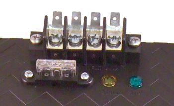
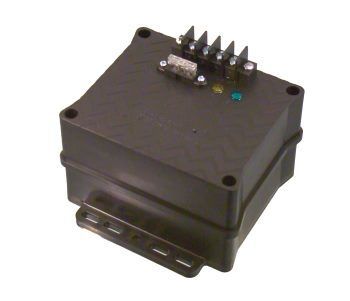
| The Backup-Jr UPS is designed to keep your equipment
from losing power or rebooting during engine start-up, in buses,
cars, and other vehicles. This ensures these spikes and sags in power don't
shorten the life of your mission critical electronics. We do this by providing
uninterrupted, clean, consistent power to your equipment, extending the life of
your electronics. The backup prevents your equipment from running the vehicle's battery down avoiding jump-starts. It switches over to the auxiliary battery when the engine is shut off and the alternator stops or the car's or bus's battery drops below 11.8 volts. This means you never have to worry about that after-market equipment leaving you with a dead battery in the morning. The Backup-Jr isolates its battery from the vehicle, so it can't be discharged by the vehicle's other electronics, and it won't try to participate in the bus's engine start-up process. The Backup-Jr DC-UPS powers your equipment in the vehicle using the vehicle's electrical system, but switches to external battery power when the car's battery is removed, stolen, or drops below a predetermined voltage, acting as a battery backup (BBU) and power conditioner. It is not necessary to run an extra sense wire to the ignition, voltage sensing takes care of the decision making. Allows for safely charging our internal battery from the car's electrical bus by isolating and current regulating the connection to the auxiliary battery. This uninterruptible power supply is designed to withstand the harsh electrical and temperature requirements of automotive equipment including spike, dropouts, load dumps, jump-starting, high and low temperatures. |
|||||||||||||||||||||||||||||||||||||||||||||||||||||||||||||||||||||||||||||||||||||||||||||||||||||||||||||||||||||||||||||
 |
|||||||||||||||||||||||||||||||||||||||||||||||||||||||||||||||||||||||||||||||||||||||||||||||||||||||||||||||||||||||||||||
| Bus battery backup system, car battery backup system, truck battery backup system | |||||||||||||||||||||||||||||||||||||||||||||||||||||||||||||||||||||||||||||||||||||||||||||||||||||||||||||||||||||||||||||
|
|
|
| |||||||||