| December 5, 2023 | ||||||||||||||||||||||||||||||||||||||||||||||||||||||||||||||||||||||||||||||||||||||||||||||||||||||||||||||||||||||||
|
||||||||||||||||||||||||||||||||||||||||||||||||||||||||||||||||||||||||||||||||||||||||||||||||||||||||||||||||||||||||
|---|---|---|---|---|---|---|---|---|---|---|---|---|---|---|---|---|---|---|---|---|---|---|---|---|---|---|---|---|---|---|---|---|---|---|---|---|---|---|---|---|---|---|---|---|---|---|---|---|---|---|---|---|---|---|---|---|---|---|---|---|---|---|---|---|---|---|---|---|---|---|---|---|---|---|---|---|---|---|---|---|---|---|---|---|---|---|---|---|---|---|---|---|---|---|---|---|---|---|---|---|---|---|---|---|---|---|---|---|---|---|---|---|---|---|---|---|---|---|---|---|
|
Custom design and manufacture of state-of-the-art battery chargers, UPS, and power supplies for OEMs in a hurry? 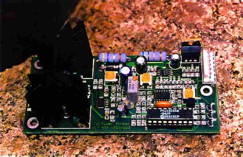
This is a microprocessor controlled SEPIC topology DC/DC converter programmed to perform as a battery charger. Theory of Operation: When input voltage is applied the following operations proceed. 1. The processor Initializes 2. All 3 LEDs come on for 1 second in self-test 3. The power Red LED turns on 4. The processor waits briefly until the output has a voltage greater than 1.0V (battery detect) 5. If the processor detects that a battery is connected, the processor then turns on the PWM with current set to high (about 1.7Amps) 6. The Yellow LED turns on indicating charging. 7. When the battery is charged to 13.65V the Green LED turns on to to indicate a full battery. 8. The battery continues to trickle charge (about 20mA) to balance and maintain the battery.
Form factor and custom features can be redesigned to OEM
requirements.
|
||||||||||||||||||||||||||||||||||||||||||||||||||||||||||||||||||||||||||||||||||||||||||||||||||||||||||||||||||||||||
|
|
|
| |||||||||