| April 18, 2023 | |||||||||||||||||||||||||||||||||||||||||||||||||||||||||||||||||||||||||||||||||||||||||||||||||||
12 volt and 24 volt Smart Battery Isolators with 80+ amps pass through and solid-state control |
180 Amp hybrid battery isolator. |
||||||||||||||||||||||||||||||||||||||||||||||||||||||||||||||||||||||||||||||||||||||||||||||||||
Battery isolator (or split charge relay) allows an auxiliary battery to be charged by the vehicle's system, yet prevents the starting battery from being run down by your equipment when the engine is off. |
 Click here for DC UPS controllers for cars and buses. |
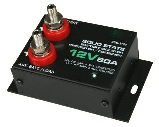
||||||||||||||||||||||||||||||||||||||||||||||||||||||||||||||||||||||||||||||||||||||||||||||||||
|
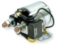
This is a solid state relay. It uses state-of-the art microprocessor solid state control of the charging and isolation functions, but uses a solid state relay to control the big currents. There are no moving parts in this unit, so it can withstand harsh operating conditions from -40°C to +50°C. The microprocessor unit constantly scans the voltage level of each of the two terminals for appropriate and timely On or Off connections. It can be used either as a battery low voltage protector or a battery isolator with manual over-ride. This solid state battery isolator uses the latest MOSFET which have the minimal internal resistance of 2mOhm which translates to a total voltage drop of 0.2V even at full load of 80A. It has an idle current consumption of 0.015A. There is no moving parts and the electronic components are conformal coated to give a safe, spark free and long lasting operation in the battery and engine electric environment. This battery-isolator is used to control battery systems that charge off the vehicle's alternator. They won't let the vehicle battery be used to power the load unless the engine is on. It will allow the extra battery to be charged at whatever rate the alternator can put out, so it needs big enough cables to do that. Big lead acid batteries when they are empty can accept 150+ amps, so rate the wires at the maximum current of the alternator (see the Q/A section below). The features are as follows: First it allows you to safely charge an external lead acid battery from the car electrical bus. It relies on the alternator's smarts to give it a good charge. In this mode it is called a split charge relay, or dual battery relay. Second it allows you to run equipment in a trailer or RV without disconnecting the vehicle power bus. While the vehicle's engine is running all equipment is running from the car's power. When the engine is turned off the trailer equipment is run from the auxiliary battery only. Third, the auxiliary battery can be a deep cycle type designed for running lights, TV, refrigerator, etc. Fourth, it can be used as a low-voltage cutout to keep the car's battery from being drawn below 12.6 volts. Fifth, no external diodes or current sense resistors are needed, the unit is a self-contained solid-state dual battery isolation relay. Note: Unlike the solenoid version of our battery isolators the voltage from the auxiliary battery can feed back to the vehicle through the body diode of the MOSFET switches. This path has a lot of resistance compared to when the MOSFETs are on, and there is a 0.6 volt diode drop, but it will feed back into the vehicle.
. Questions and Answers 1. Q: What is the intended application? A: Automatic separation and connection of main (starter) and auxiliary batteries during charging and discharging according to the state of charge of the main battery. Dual battery or multi-banks battery systems such as four wheel vehicles, RV, hunting vehicles, solar charged batteries, ham radio, etc. 2. Q: How does the module work? A: The brain of the isolator is a microprocessor unit and voltage sensing circuitry. It constantly checks the voltage of the main starting battery for connection and disconnection of the solid state relay with appropriate time delays. 3. Q: What is the principle of operation? A: In the normal state the main and auxiliary batteries are separated by the isolator. The control box will constantly monitor the main battery voltage until it is charged by the alternator to 13.6 volts and stays there or above for 15 seconds. The isolator will then connect the two batteries in parallel through the solenoid contactor to allow both batteries to be charged. When there is a heavy or sudden drain on either battery (due to large loads such as starting the vehicle or shutting down of the alternator) the voltage across the main battery drops to below 12.6 volts and the batteries are separated by turning off the relay coil. The cycle will repeat to ensure full protection and priority charging of the main battery at all times and to allow safe charging of the auxiliary batteries. Priority is given to the main (starting motor) battery to be charged first. There is an over ride connector that can be used to connect the two batteries temporarily to be used for emergency purposes, for example if you want to leave the vehicle lights on for an extended period of time, or the starter battery is not strong enough to start the car by itself. 4. Q: What are the four types of battery isolators? A: The first is simply a switch to remove the auxiliary battery from the car's electrical circuit. The disadvantage of this is that humans (such as me) forget to turn the switch on and off as appropriate. The second is a diode isolator. This is simple, it allows current to flow from the circuit with the highest voltage. The disadvantages of these are limited current, and the fact that there is always a half-volt drop across the diodes. This will dissipate 40 watts when 80 amps are flowing, so it is wasteful unless you are using that power to heat a trailer. It also lowers the charge voltage going to the auxiliary battery which severely decreases its maximum charge rate. The third is a solid-state relay system that uses control circuitry and power MOSFETS to do the switching. This eliminates the diode drop, though there is still some resistance in the power transistor conduction channels to cause heat and to limit the amount of current to flow. This is how the PST-SSB2180 and PST-SSB2280 work. The fourth is our hybrid system that uses a microprocessor circuit to monitor the charging and discharging and a rugged, reliable solenoid contactor (relay) to allow enormous currents to flow without damaging the electronics. 5. Q: What size wires should I use? A: As big as is reasonable. Our web page /Wire_Size.htm recommends 7 gauge to 2 gauge to transmit 80 amps, depending on how far you are going. If you are going short distances you can play with smaller wires, but 3 feet of 6 AWG wire will drop 0.09 volts when transmitting 80 amps. When using the calculator on our Wire Size page note that the voltage drop only depends on the gauge and the current, not on the input voltage. You should try to have the total voltage drop in the wires be less than 0.25 volts. If you are not going to draw that much current then the wire gauge can be smaller. For example, if you have an alternator that will only supply 60 amps and you aren't going to be drawing more than that on your load you can rate the wires for 60 amps instead of 80 amps. 6. Q: Which of the terminals get connected to which wires? A: The connections are clearly labeled on the top of the isolator, one positive to the main and the other to the load/auxiliary battery. 7. Q: Does the isolator isolate the two batteries in both directions? A: No, the isolator prevents the starting motor battery from discharging through the auxiliary load, but it does not prevent the auxiliary battery from feeding back into the vehicle's electrical bus. 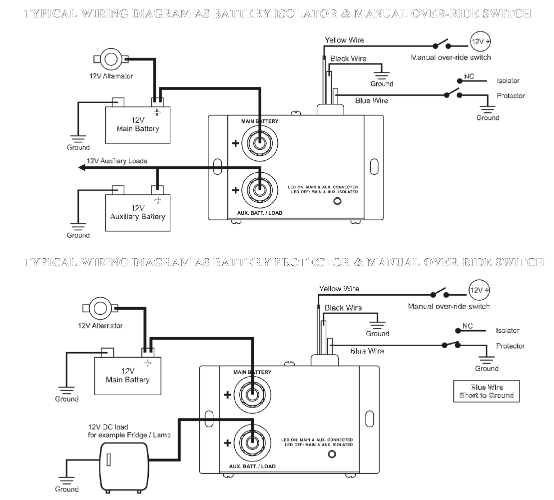 |
|||||||||||||||||||||||||||||||||||||||||||||||||||||||||||||||||||||||||||||||||||||||||||||||||||
|
|
|
| |||||||||