April 18, 2023
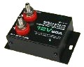
Inexpensive 12 volt Smart Battery Isolator with 150+ amps pass-through and solid-state control |
 Click here for a solid state 80 amp battery isolator, 12V or 24V |
||||||||||||||||||||||||||||||||||||||||||||||||||||||
 Battery isolator (or split charge relay) allows an auxiliary battery to be charged by the vehicle's system, yet not participate in engine starting. It also prevents the starting battery from being run down by your equipment when the engine is off. |
 Click here for DC UPS controllers for cars and buses. |
||||||||||||||||||||||||||||||||||||||||||||||||||||||
This is a hybrid device. It uses state-of-the art microprocessor solid state control of the charging and isolation functions, but uses a solid tungsten points contactor relay to control the big currents. Seriously, we can design a solid-state battery isolator, but we like the forgiving nature of a big contactor. If you have a 1500 amp spike, the relay's terminals can probably handle that, whereas MOFETS will simply fail, and when one fails the rest cascade like a waterfall. The worst thing that can happen with a contactor is that the relay contacts will weld together if the big over-current happens while the contactor is trying to open. This almost never happens, but this (to us) is a fail-safe condition, the auxiliary battery will still charge, and to fix it requires only some judicious banging on the relay to get it working again. This hybrid system is really the best of both worlds, solid-state control and solid-metal contacts.This battery-isolator is used to control extra battery systems that charge off the vehicle's alternator. The isolator won't let the auxiliary batteries be discharged by the vehicle's gadgets. Neither will he house battery be used to start the car (unless asked to). It will allow the extra battery to be charged at whatever rate the alternator can put out, so it needs big enough cables to do that. Big lead acid batteries when they are empty can accept 150+ amps, so rate the wires at the maximum current of the alternator (see the Q/A section below). It can be used as a trailer battery charging module. The features are as follows:First, it allows you to safely charge an external lead acid battery from the car electrical bus. It relies on the alternator's smarts to give it a good charge. In this mode it is called a split-charge relay, or dual-battery relay.Second it isolates the extra battery from the car so it won't be discharged by the car electronics, and it won't try to participate in starting the car. (There is an emergency function that will allow the spare battery to feed back to the starting system if the starting battery is dead.) In this mode it is a dual-battery relay. Third it allows you to run equipment in a trailer or RV from the extra battery without having to remember to disconnect it from the vehicle's power bus. While the vehicle's engine is running all equipment is running from the car's power. When the engine is turned off the trailer equipment is run from the auxiliary battery Fourth there is an emergency function that will allow the spare battery to feed back to the starting system if the starting battery is dead or weak. This allows you to give the system a boost in cold weather or if a squirrel snuck into the cab and left the lights on all night. Fifth, the auxiliary battery can be a deep cycle type designed for running lights, TV, refrigerator, etc. The starting motor battery will fail quickly if deep-discharged. Sixth, it can be used as a low-voltage cutout to keep the car's battery from being drawn below 12.6 volts. Seventh, no external diodes or current sense resistors are needed, the unit is a self-contained dual battery isolation relay.
 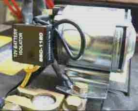 This shows the dual battery isolator/combiner mounted on the negative terminal of a car's battery. This is not necessarily the best place to put it, but it does work. ReviewHello, I have the sbc1120 isolator installed for more than a year now and it works like a champ. On two occasions I have had to start my truck using the AUX battery and connector. I changed the connector on the Yellow wire to a to a clip-on type to avoid needing two people to start the truck. Thanks, Glen A.. (happy customer ) Questions and Answers1. Q: What is the intended application?A: Automatic separation and connection of main (starter) and auxiliary batteries during charging and discharging according to the state of charge of the main battery. Dual battery or multi-banks battery systems such as four wheel vehicles, RV, hunting vehicles, solar charged batteries, ham radio, etc.2. Q: How does the module work?A: The brain of the isolator is a match-box sized potted control box with a microprocessor unit and voltage sensing circuitry. It constantly checks the voltage of the main starting battery for connection and disconnection of the mounted solenoid contactor with appropriate time delays. The merging of the electro-mechanical solenoid valve for large current capability, and the lowest possible insertion loss, with a smart microprocessor control combine to make a reliable, precise and cost effective battery isolator / separator /combiner for use with multiple battery banks.3. Q: What is the principle of operation?A: In the normal state the main and auxiliary batteries are separated by the isolator.The control box will constantly monitor the main battery voltage until it is charged to 13.6 volts and stays there or above for 15 seconds. The isolator will then connect the two batteries in parallel through the solenoid contactor to allow both batteries to be charged. When there is a heavy or sudden drain on either battery (due to large loads such as starting the vehicle or shutting down of the alternator) the voltage across the main battery drops to below 12.6 volts and the batteries are separated by turning off the relay coil. The cycle will repeat to ensure full protection and priority charging of the main battery at all times and to allow safe charging of the auxiliary batteries. Priority is given to the main (starting motor) battery to be charged first. There is an over ride connector that can be used to connect the two batteries at all times to be used for emergency purposes, for example if you want to leave the vehicle lights on for an extended period of time, or the starter battery is not strong enough to start the car by itself. 4. Q: What are the four types of battery isolators?A: The first is simply a switch to remove the auxiliary battery from the car's electrical circuit. The disadvantage of this is that humans (such as me) forget to turn the switch on and off as appropriate.The second is a diode isolator. This is simple, it allows current to flow from the circuit with the highest voltage. The disadvantages of these are limited current, and the fact that there is always a half-volt drop across the resistors. This will dissipate 50 watts when 100 amps are flowing, so it is wasteful unless you are using that power to heat the trailer. It also lowers the charge voltage going to the auxiliary battery which severely decreases its maximum charge rate. The third is a solid-state relay system that uses control circuitry and power MOSFETS to do the switching. This eliminates the diode drop, though there is still some resistance in the power transistor conduction channels to cause heat and to limit the amount of current to flow. These are susceptible to damage from voltage and current spikes and can be damaged by drawing too much current through them. Due to the high cost of high-current MOSFETs these isolators are about twice the price and half the pass-through current of the hybrid unit that we sell. The fourth is our hybrid system that uses a microprocessor circuit to monitor the charging and discharging and a rugged, reliable solenoid contactor (relay) to allow enormous currents to flow without damaging the electronics. This has the advantage of high precision, high reliability and low cost. 5. Q: What size wires should I use?A: As big as is reasonable. Our web page voltage drop calculator /Wire_Size.htm recommends 2 gauge to 00 gauge to transmit 180 amps, depending on how far you are going. If you are going short distances you can play with smaller wires, but 3 feet of 6 AWG wire will drop 0.2 volts when transmitting 180 amps. When using the calculator on our Wire Size page note that the voltage drop only depends on the gauge and the current, not on the input voltage. You should try to have the total voltage drop in the wires be less than 0.25 volts.If you are not going to draw that much current then the wire gauge can be smaller. For example, if you have an alternator that will only supply 75 amps and you aren't going to be drawing more than that on your load you can rate the wires for 75 amps instead of 180 amps. 6. Q: Which of the terminals get connected to which wires?A: It doesn't matter as long as the yellow and black wires go to the small terminals and the positive input goes to the same big terminal as the module is connected to.7. Q: Why does the solenoid get hot?A: It is dissipating 12 watts to keep the coil activated, so it can get pretty hot (up to 140 degrees F, 60°C depending on the air temperature and the air flow). Make sure you mount it in a place that won't allow some one to accidentally touch it and it has some heat dissipation such as free air flow.8. Why doesn't the relay turn off immediately when the engine turns off?A: The starting-motor battery has to drop to 12.6 volts before the module turns off the solenoid. This is to prevent oscillation under load. When the car's battery is discharged 2-3% the battery will drop to 12.6 volts and the solenoid will release. This can happen pretty fast if there is a load on the auxiliary battery, but if there is no load then only the 12 watt load of the solenoid is left to draw down the car's battery to 97-98% of its capacity. For a large car or truck battery this can take from 45 minutest to 6 hours. Remember, the purpose of the isolator is to keep the starting-motor battery fresh while discharging the auxiliary battery, but we can't keep from discharging the starting-motor battery a little bit without causing other problems.9. Q: Do you have one for 24 volt vehicles?A: Yes, we have a solid state battery isolator that works in 24 volt systems, click here.10. Is the auxiliary battery safe from overcharge?A: The alternator will also protect the auxillary battery from being overcharged. 11. What size auxiliary battery shall I use?Any size sealed lead acid or other deep cycle battery can be used with this system. Connection diagrams: 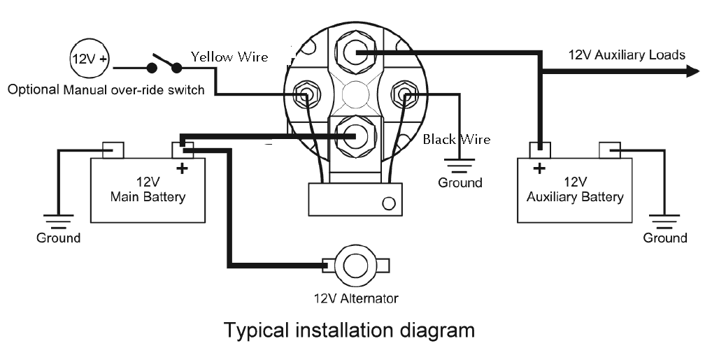 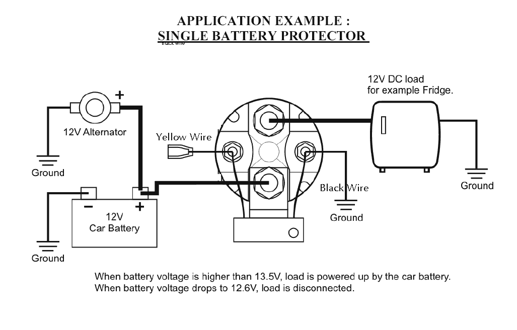 |
|||||||||||||||||||||||||||||||||||||||||||||||||||||||
|
|
|
| |||||||||