CHAPTER 3.
MANUFACTURE OF STORAGE BATTERIES.
To supply the great number of batteries needed for gasoline automobiles, large companies have been formed. Each company has its special and secret processes which it will not reveal to the public. Only a few companies, however, supply batteries in any considerable quantities, the great majority of cars being supplied with batteries made by not more than five or six manufacturers. This greatly reduces the number of possible different designs in general use today.The design and dimensions of batteries vary considerably, but the general constructions are similar. The special processes of the manufacturers are of no special interest to the repairman, and only a general description will be given here.
A starting and lighting battery consists of the following principal parts:
- Plates
- Separators
- Electrolyte
- Jars
- Covers
- Cell Connectors and Terminals
- Case
Of the two general types of battery plates, Faure and Plante, the Faure, or pasted type, is universally used on automobiles. In the manufacture of pasted plates there are several steps which we shall describe in the order in which they are carried out.
Casting the Grid. The grid is the skeleton of the plate. It performs the double function of supporting the mechanically weak active material and of conducting the current. It is made of a lead antimony alloy which is melted and poured into a mould. Pure lead is too soft and too easily attacked by the electrolyte, and antimony is added to give stiffness, and resistance to the action of the electrolyte in the cell. The amount of antimony used varies in different makes but probably averages 8 to 10%.
The casting process requires considerable skill, the proper composition of the metal and the temperature of both metal and moulds being of great importance in securing perfect grids, which are free from blowholes, and which have a uniform structure and composition. Some manufacturers cast two grids simultaneously in each mould, the two plates being joined to each other along the bottom edge.
Trimming the Grids. When the castings have cooled, they are removed from the moulds and passed to a press or trimming machine which trims off the casting gate and the rough edges. The grids are given a rigid inspection, those having shrunken or missing ribs or other defects being rejected. The grids are now ready for pasting.
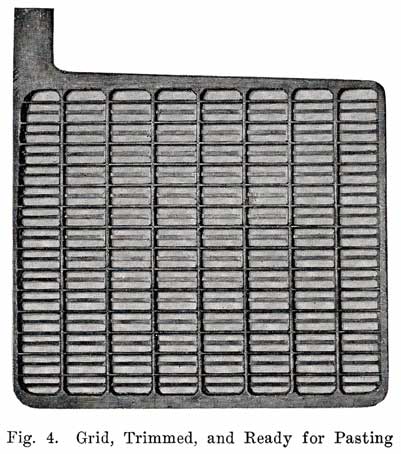
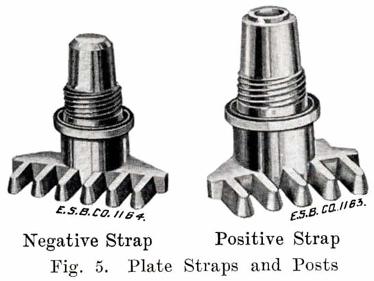
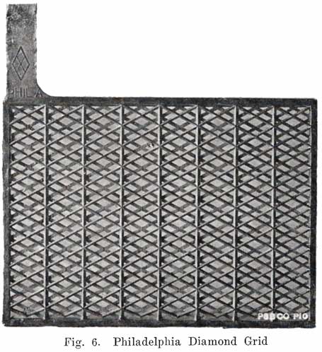
Fig. 4 shows a grid ready for pasting. The heavy lug at one upper corner is the conducting lug, for carrying the current to the strap, Fig. 5, into which the lugs are burned when the battery is assembled. The straps are provided with posts, to which the intercell connectors and terminal connectors are attached. The vertical ribs of the grids extend through the plate, providing mechanical strength and conductivity, while the small horizontal ribs are at the surface and in staggered relation on opposite faces. Both the outside frames and the vertical ribs are reinforced near the lug, where the greatest amount of current must be carried.The rectangular arrangement of ribs, as shown in Fig. 4, is most generally used, although, there are other arrangements such as the Philadelphia "Diamond" grid in which the ribs form acute angles, giving diamond shaped openings, as shown in Fig. 6.
Pastes. There are many formulas for the pastes, which are later converted into active material, and each is considered a trade secret by the manufacturer using it. The basis of all, however, is oxide of lead, either Red Lead (Pb304), Litharge (PbO), or a mixture of the two, made into a paste with a liquid, such as dilute sulphuric acid. The object of mixing the oxides with the liquid is to form a paste of the proper consistency for application to the grids, and at the same time introduce the proper amount of binding, or setting agent which will give porosity, and which will bind together the active material, especially in the positive plate. Red lead usually predominates in the positive paste, and litharge in the negative, as this combination requires the least energy in forming the oxides to active material.
The oxides of lead used in preparing the pastes which are applied to the grids are powders, and in their dry condition could not be applied to the grids, as they would fall out. Mixing them with a liquid to make a paste gives them greater coherence and enables them to be applied to the grids. Sulphuric acid puts the oxides in the desired pasty condition, but has the disadvantage of causing a chemical action to take place which changes a considerable portion of the oxides to lead sulphate, the presence of which makes the paste stiff and impossible to apply to the grids. When acid is used, it is therefore necessary to work fast after the oxides are mixed with sulphuric acid to form the paste.In addition to the lead oxides, the pastes may contain some binding material such as ammonium or magnesium sulphate, which tends to bind the particles of the active material together. The paste used for the negatives may contain lamp black to give porosity.
Applying the Paste. After the oxides are mixed to a paste they are applied to the grids. This is done either by hand, or by machine In the hand pasting process, the pastes are applied from each face of the grid by means of a wooden paddle or trowel, and are smoothed off flush with the surface of the ribs of the grid. This work is done quickly in order that the pastes may not stiffen before they are applied.
U. S. L. plates are pasted in a machine which applies the paste to the grid, subjecting it at the same time to a pressure which forces it thoroughly into the grid, and packs it in a dense mass.
Drying the Paste. The freshly pasted plates are now allowed to dry in the air, or are dried by blowing air over them. In any case, the pastes set to a hard mass, in which condition the pastes adhere firmly to the grids. The plates may then be handled without a loss of paste from the grids.
Forming. The next step is to change the paste of oxides into the active materials which make a cell operative. This is called "forming" and is really nothing but a prolonged charge, requiring several days. In some factories the plates are mounted in tanks, positive and negative plates alternating as in a cell. The positives are all connected together in one group and the negatives in another, and current passed through just as in charging a battery. In other factories the positives and negatives are formed in separate tanks against "dummy" electrodes.The passing of the current slowly changes the mixtures of lead oxide and lead sulphate, forming brown peroxide of lead (PbO2), on the positive plate and gray spongy metallic lead on the negative. The formation by the current of lead peroxide and spongy lead on the positive and negative plates respectively would take place if the composition of the two pastes were identical. The difference in the composition of the paste for positive and negative plates is for the purpose of securing the properties of porosity and physical condition best suited to each.
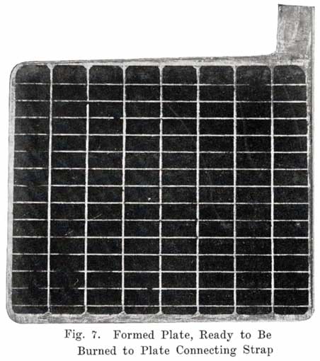
When the forming process is complete, the plates are washed and dried, and are then ready for use in the battery. If the grids of two plates have been cast together, as is done by some manufacturers, these are now cut apart, and the lugs cut to the proper height. The next step is to roll, or press the negatives after they are removed from the forming bath so as to bring the negative paste, which has become roughened by gassing that occurred during the forming process, flush with the surface of the ribs of the grid. A sufficient amount of sulphate is left in the plates to bind together the active material. Without this sulphate the positive paste would simply be a powder and when dry would fall out of the grids like dry dust. Fig. 7 shows a formed plate ready to be burned to the strap.
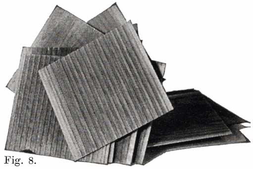
In batteries used both for starting and for lighting, separators made of specially treated wood are largely used. See Fig. 8. The Willard Company has adopted an insulator made of a rubber fabric pierced by thousands of cotton threads, each thread being as long as the separator is thick. The electrolyte is carried through these threads from one side of the separator to the other by capillary action, the great number of these threads insuring the rapid diffusion of electrolyte which is necessary in batteries which are subjected to the heavy discharge current required in starting.In batteries used for lighting or ignition, sheets of rubber in which numerous holes have been drilled are also used, these holes permitting diffusion to take place rapidly enough to perform the required service satisfactorily, since the currents involved are much smaller than in starting motor service.
|
Fig. 8. A Pile of Prepared Wooden Seperators Ready to be Put Between the Positive and Negative Plates to Form the Complete Element. |
For the wooden separators, porous wood, such as Port Orford cedar, basswood, cypress, or cedar is used. Other woods such as redwood and cherry are also used. The question is often asked "which wood makes the best separators?" This is difficult to answer because the method of treating the wood is just as important as is the kind of wood. The wood for the separators is cut into strips of the correct thickness. These strips are passed through a grooving machine which cuts the grooves in one side, leaving the other side smooth. The strips are next sawed to the correct size, and are then boiled in a warm alkaline solution for about 24 hours to neutralize any organic acid, such as acetic acid, which the wood naturally contains. Such acids would cause unsatisfactory battery action and damage to the battery.The Vesta separator, or "impregnated mat," is treated in a bath of Barium salts which form compounds with the wood and which are said to make the separators strong and acid-resisting.
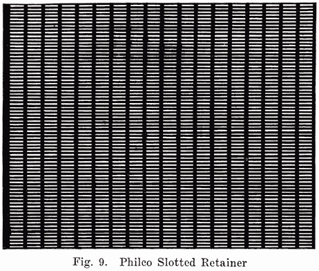
Some batteries use a double separator, one of which is the wooden separator, while the other consists of a thin sheet of hard rubber containing many fine perforations. This rubber sheet is placed between the positive plate and the wooden separator. A recent development in the use of an auxiliary rubber separator is the Philco slotted retainer which is placed between the separators and the positives in Philadelphia Diamond Grid Batteries. Some Exide batteries also use slotted rubber separators. The Philco slotted retainer consists of a thin sheet of slotted hard rubber as shown in Fig. 9. The purpose of the retainer is to hold the positive active material in place and prevent the shedding which usually occurs. The slots in the retainer are so numerous that they allow the free passage of electrolyte, but each slot is made very narrow so as to hold the active material in the plates.
Little need be said here about the electrolyte, since a full description is given elsewhere. See page 222. Acid is received by the battery manufacturer in concentrated form. Its specific gravity is then 1.835. The acid commonly used is made by the "contact" process, in which sulphur dioxide is oxidized to sulphur trioxide, and then, with the addition of water, changed to sulphuric acid. The concentrated acid is diluted with distilled water to the proper specific gravity.
The jars which contain the plates, separators, and electrolyte are made of a tough, hard rubber compound. They are made either by the moulding process, or by -wrapping sheets of rubber compound around metal mandrels. In either case the jar is subsequently vulcanized by careful heating at the correct temperature.The battery manufacturers do not, as a rule, make their own jars, but have them made by the rubber companies who give the jars a high voltage test to detect any flaws, holes, or cracks which would subsequently cause a leak. The jars as received at the battery maker's factory are ready for use.
Across the bottom of the jar are several stiff ribs which extend up into the jar so as to provide a substantial support for the plates, and at the same time form several pockets below the plates in which the sediment resulting from shedding of active material from the plates accumulates.
No part of a battery is of greater importance than the hard rubber cell covers, from the viewpoint of the repairman as well as the manufacturer. The repairman is concerned chiefly with the methods of sealing the battery, and no part of his work requires greater skill than the work on the covers. The manufacturers have developed special constructions, their aims being to design the cover so as to facilitate the escape of gas which accumulates in the upper part of a cell during charge, to provide space for expansion of the electrolyte as it becomes heated, to simplify inspection and filling with pure water, to make leak proof joints between the cover and the jar and between the cover and the lead posts which project through it, and to simplify the work of making repairs.Single and Double Covers. Modern types of batteries have a single piece cover, the edges of which are made so as to form a slot or channel with the inside of the jar, into which is poured sealing compound to form a leak proof joint. This construction is illustrated. in Exide, Fig. 1.5; Vesta, Fig. 264; Philadelphia Diamond Grid, Fig. 256; U. S. L., Figs. 11 and 244; and Prest-0-Lite, Fig. 247, batteries. Exide batteries are also made with a double flange cover, in which the top of the jar fits between the two flanges. In single covers, a comparatively small amount of sealing compound is used, and repair work is greatly simplified.
In the Eveready battery, Fig. 262, compound is poured over the entire cover instead of around the edges. This method requires a considerable amount of sealing compound.
The use of double covers is not as common as it was some years ago. This construction makes use of two flat pieces of hard rubber. In such batteries a considerable amount of sealing compound is used. This compound is poured on top of the lower cover to seal the battery, the top cover serving to cover up the compound and brace the posts. Fig. 10 illustrates this construction.
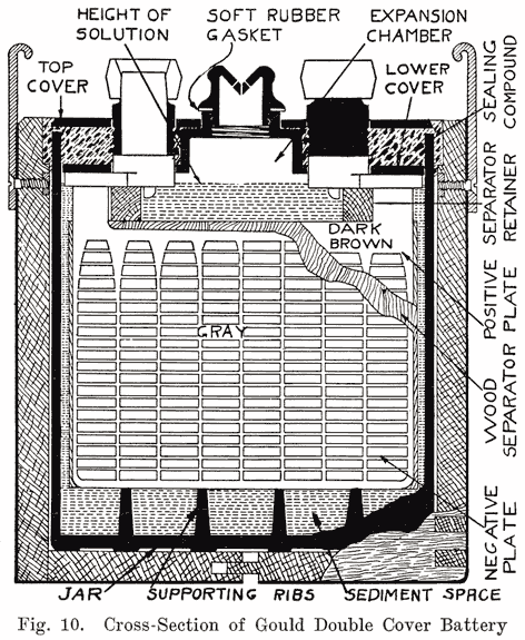
Sealing Around the Posts. Much variety is shown in the methods used to secure a leak proof joint between the posts and the cover. Several methods are used. One of these uses the sealing compound to make a tight joint. Another has lead bushings which are screwed up into the cover or moulded in the cover, the bushings being burned together with the post and cell connector. Another method has a threaded post, and uses a lead alloy nut with a rubber washer to make a tight joint. Still another method forces a lead collar down over the post, and presses the cover down on a soft rubber gasket.Using Sealing Compound. Some of the batteries which use sealing compound to make a tight joint between the cover and the post have a hard rubber bushing shrunk over the post. This construction is used in Gould batteries, as shown in Fig. 10, and -in the old Willard double cover batteries. The rubber bushing is grooved horizontally to increase the length of the sealing surface.
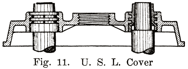
Other batteries that use sealing compound around the posts have grooves or "petticoats" cut directly in the post and have a well around the post into which the sealing compound is poured. This is the construction used in the old Philadelphia Diamond Grid battery, as shown in Fig. 254.Using Lead Bushings. U. S. L. batteries have a flanged lead bushing which is moulded directly into the cover, as shown in Fig. 11. In assembling the battery, the cover is placed over the post, and the cell connector is burned to both post and bushing.
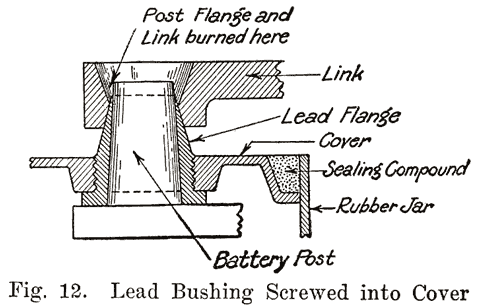
In older type U. S. L. batteries a bushing was screwed up through the cover, and then burned to the post and cell connector.An old type Prest-O-Lite battery used a lead bushing which screwed up through the cover similarly to the U. S. L. batteries. Fig. 12 illustrates this construction. The SJWN and SJRN Willard Batteries used a lead insert. See page 424.
The modern Vesta batteries use a soft rubber gasket under the cover, and force a lead collar over the post, which pushes the cover down on the gasket. The lead collar and post "freeze" together and. make an acid proof joint. See page 413. The Westinghouse battery uses a three part seal consisting of a lead washer which is placed around the post, a U shaped, soft gum washer which is placed between the post and cover, and a tapered lead sleeve, which presses the washer against the post and the cover. See page 417.
The Prest-O-Lite Peened Post Seal. All Prest-O-Lite batteries designated as types WHN, RHN, BHN and JFN, have a single moulded cover which is locked directly on to the posts. This is done by forcing a solid ring of lead from a portion of the post down into a chamfer in the top of the cover. This construction is illustrated in Fig. 247.Batteries Using Sealing Nuts. The Exide batteries have threaded posts. A rubber gasket is placed under the cover on a shoulder on the post. The nut is then turned down on the post to force the cover on the gasket. This construction is illustrated in Fig. 239. The Titan battery uses a somewhat similar seal, as shown in Fig. 293.
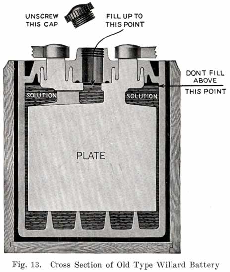
Some of the older Willard batteries have a chamfer or groove in the under, side of the cover. The posts have a ring of lead in the base which fits up into the. groove in the cover to make a tight joint. This is illustrated in Fig. 13. The later Willard constructions, using a rubber gasket seal and a lead cover insert, are illustrated in Figs. 278 and 287.
Filling Tube or Vent Tube Construction. Quite a number of designs have been developed in the construction of the filling or vent tube. In double covers, the tube is sometimes a separate part which is screwed into the lower cover. In other batteries using double covers, the tube is an integral part of the cover, as shown in Fig. 10. In all single covers, the tube is moulded integral with the cover.
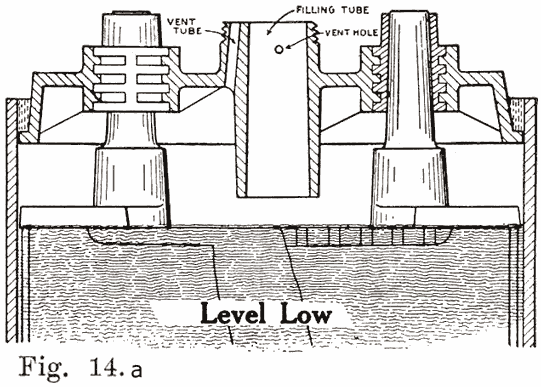
Several devices have been developed to make it impossible to overfill batteries. This has been done by the U. S. L. and Exide companies on older types of batteries, their constructions being described as follows:In old U. S. L. batteries, a small auxiliary vent tube is drilled, as shown in Fig. 14. When filling to replace evaporation, this vent tube prevents overfilling.
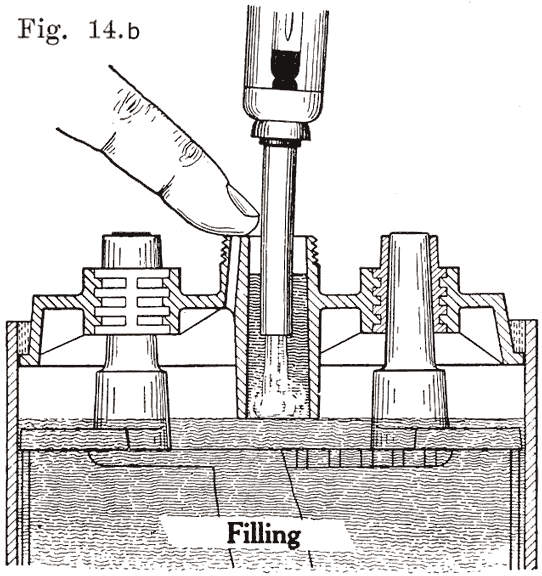
A finger is placed over the auxiliary vent tube shown in Fig. 14. The water is then poured in through the filling or vent tube. When the water reaches the bottom of the tube, the air imprisoned in the expansion chamber can no longer escape. Consequently the water can rise no higher in this chamber, but simply fills up the tube. Water is added till it reaches the top of the tube. The finger is then removed from the vent tube. This allows the air to escape from the expansion chamber. The water will therefore fall in the filling or vent tube, and rise slightly in the expansion chamber. The construction makes it impossible to overfill the battery, provided that the finger is held on the vent hole as directed.
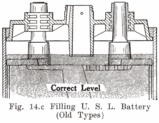
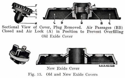
Figure 15 shows the Non-Flooding Vent and Filling Plug used in the older type Exide battery, and in the present type LXRV. The new Exide cover, which does not use the non-flooding feature, is also shown. The old construction is described as follows:
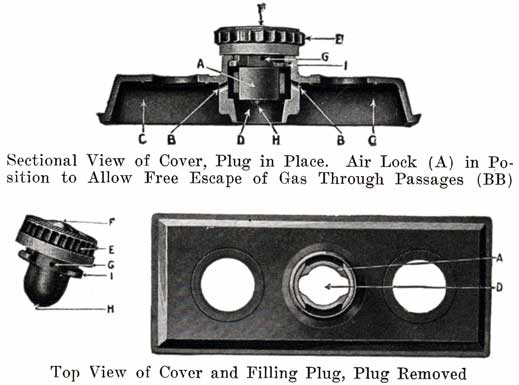
From the illustrations of the vent and filling plug, it will be seen that they provide both a vented stopper (vents F, G, H), and an automatic device for the preventing of overfilling and flooding. The amount of water that can be put into the cell is limited to the exact amount needed to replace that lost by evaporation. This is accomplished by means of the hard rubber valve (A) within the cell cover and with which the top of the vent plug (E) engages, as shown in the illustrations. The action of removing the plug (E) turns this valve- (A), closing the air passage (BB), and forming an air tight chamber (C) in the top of the cell. When water is poured in, it cannot rise in this air space (C) so as to completely fill the cell. As soon as the proper level is reached, the water rises in the filling tube (D) and gives a positive indication that sufficient water has been added. Should, however, the filling be continued, the excess will be pure water only, not acid. On replacing the plug (E), valve (A) is automatically turned, opening the air passages (BB), leaving the air chamber (C) available for the expansion of the solution, which occurs when the battery is working.Generally the filling or vent tube is so made that its lower end indicates the correct level of electrolyte above the plates, In adding water, the level of the electrolyte is brought up to the bottom of the filling tube. By looking down into the tube, it can be seen when the electrolyte reaches the bottom of the tube.
Vent Plugs, or Caps. Vent plugs, or caps, close up the filling or vent tubes in the covers. They are made of hard rubber, and either screw into or over the tubes, or are tightened by a full or partial turn, as is done in Exide batteries. In the caps are small holes which are so arranged that gases generated within the battery may escape, but acid spray cannot pass through these holes. It is of the utmost importance that the holes in the vent caps be kept open to allow the gases to escape.
The wooden case in which the cells are placed is usually made of kiln dried white oak or hard maple. The wood is inspected carefully, and all pieces are rejected that are weather- checked, or contain worm-holes or knots. The wood is sawed into -various thicknesses, and then cut to the proper lengths and widths. The wood is passed through other machines that cut in the dovetails, put the tongue on the bottom for the joints, stamp on the part number, drill the holes for the screws or bolts holding the handles, cut the grooves for the sealing compound, etc. The several pieces are then assembled and glued together. The finishing touches are then put on, these consisting of cutting the cases to the proper heights, sandpapering the boxes, etc. The cases are then inspected and are ready to be painted.A more recent development in case construction is a one-piece hard rubber case, in which the jars and case are made in one piece, the cell compartments being formed by rubber partitions which form an integral part of the case. This construction is used in several makes of Radio "A" batteries, and to some extent in starting batteries.
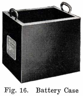
Asphaltum paint is generally used for wooden cases, the bottoms and tops being given three, coats, and the sides, two. The number of coats of paint varies, of course, in the different factories. The handles are then put on by machinery, and the case, Fig. 16, is complete, and ready for assembling.The first step in assembling a battery is to burn the positive and negative plates to their respective straps, Fig. 5, forming the positive and negative "groups," Fig. 2. This is done by arranging a set of plates and a strap in a suitable rack which holds them securely in proper position, and then melting together the top of the plate lugs and the portion of the strap into which they fit with a hot flame.
A positive and a negative group are now slipped together and the separators inserted. The grooved side of the wood separator is placed toward the positive plate and when perforated rubber sheets are used these go between the positive and the wood separator. The positive and negative "groups" assembled with the separators constitute the "element," Fig. 3.
Before the elements are placed in the jars they are carefully inspected to make sure that no separator has been left out. For this purpose the "Exide" elements are subjected to an electrical test which rings a bell if a separator is missing, this having been found more infallible than trusting to a man's eyes.
In some batteries, such as the Exide, Vesta, and Prest-O-Lite batteries, the cover is placed on the element and made fast before the elements are placed in the jars. In other batteries, such as the U. S. L. and Philadelphia batteries, the covers are put on after the elements are placed in the jars.
After the element is in the jar and the cover in position, sealing compound is applied hot so as to make a leak proof joint between jar and cover.
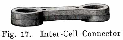
The completed cells are now assembled in the case and the cell connectors, Fig. 17, burned to the strap posts. After filling with electrolyte the battery is ready to receive its "initial charge," which may require from one day to a week. A low charging rate is used, since the plates are generally in a sulphated condition when assembled. The specific gravity is brought up to about 1.280 during this charge. Some makers now give the battery a short high rate discharge test (see page 266), to disclose any defects, and just before sending them out give a final charge. The batteries are often "cycled" after being assembled, this consisting in discharging and recharging the batteries several times to put the active material in the best working condition. If the batteries are to be shipped "wet," they are ready for shipping after the final charge and inspection. Batteries which are shipped "dry" need to have more work done upon them.
Preparing Batteries for Dry Shipment
There are three general methods of "dry" shipment. The first method consists of sending cases, plates, covers, separators, etc., separately, and assembling them in the service stations. Sometimes these parts are all placed together, as in a finished battery, but without the separators, the covers not being sealed, or the connectors and terminals welded to the posts. This is a sort of "knock-down" condition. The plates used are first fully charged and dried.The second method consists of assembling a battery complete with plates, separators, and electrolyte, charging the battery, pouring out the electrolyte, rinsing with distilled water, pouring out the water and screwing the vent plugs down tight. The vent holes in these plugs are sealed to exclude air. The moisture left in the battery when the rinsing water was poured out cannot evaporate, and the separators are thus kept in a moistened condition.
The third method is the Willard "Bone Dry" method, and consists of assembling the battery complete with dry threaded rubber separators and dry plates, but without electrolyte. The holes in the vent plugs are not sealed, since there is no moisture in the battery. Batteries using wooden separators cannot be shipped "bone-dry," since wooden separators must be kept moist.
When the battery is on the car it is necessary to have some form of detachable connection to the car circuit and this is accomplished by means of "terminal connectors," Fig. 18, of which there are many types.
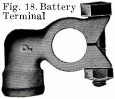
Many types of terminals are in two parts, one being permanently attached to the car circuit and the other mounted permanently on the battery by welding it to the terminal post, the two parts being detachably joined by means of a bolted connection.In another type of terminal, the cable is soldered directly to the terminal which is lead burned to the cell post. In this construction there is very much less chance of corrosion taking place, and it is therefore a good design.
The wisest thing for the battery shop owner to do is to get a contract as official service station for one of. the well known makes of batteries. The manufacturers of this battery will stand behind the service station, giving it the benefits of its engineering, production, and advertising departments, and boost the service station's business, helping to make it a success.Within the past year or so, however, some battery repairmen have conceived the idea that they do not need the backing of a well organized factory, and have decided to build up their own batteries. Some of them merely assemble batteries from parts bought from one or more manufacturers. If all the parts are made by the same company, they will fit together, and may make a serviceable battery. Often, however, parts made by several manufacturers are assembled in the same battery. Here is where trouble is apt to develop, because it is more than likely that jars may not fit well in the case; plates may not completely fill the jars, allowing too much acid space, with the results that specific gravity readings will not be reliable, and the plates may be overworked; plate posts may not fit the cover holes, and so on. If such a "fabricated" battery goes dead because of defective material, there is no factory back of the repairman to stand the loss.
If the repairman wishes to assemble batteries, he should be very careful to buy the parts from a reliable manufacturer, and he should be especially careful in buying separators, as improperly treated separators often develop acetic acid, which dissolves the lead of the plates very quickly and ruins the battery. Batteries made in this way are good for rental batteries, or "loaners." These batteries are assembled and charged just as are batteries which have been in dry storage, see page 241.
If the repairman who "fabricates" batteries takes chances, the man who attempts to actually make his own battery plates is certainly risking his business and reputation. There are several companies which sell moulds for making plate grids. One even sells cans of lead oxides to enable the repairman to make his own plate paste. Even more foolhardy than the man who wishes to mould plate grids is the man who wishes to mix the lead oxides himself. Many letters asking for paste formulas have been received by the author. Such formulas can never be given, for the author does not have them. Paste making is a far more difficult process than many men realize. The lead oxides which are used must be tested and analyzed carefully in a chemical laboratory and the paste formulas varied according to the results of these tests. The oxides must be carefully weighed, carefully handled, and carefully analyzed. The battery service station does not have the equipment necessary to do these things, and no repairman should ever attempt to make plate paste, as trouble is bound to follow such attempts. A car owner may buy a worthless battery once, but the next time he will go to some other service station and buy a good battery
No doubt many repairmen are as skillful and competent as the workers in battery factories, but the equipment required to make grids and paste is much too elaborate and expensive for the service station, and without such equipment it is impossible to make a good battery.
The only battery parts which may safely be made in the service station are plate straps and posts, intercell connectors, and cell terminals. Moulds for making such parts are on the market, and it is really worth while to invest in a set. The posts made in such moulds are of the plain tapered type, and posts which have special sealing and locking devices, such as the Exide, Philadelphia, and Titan cannot be made in them.
|
|
|
| |||||||||