Section II
Shop Equipment
Shop Methods
CHAPTER 11
SHOP EQUIPMENT
Any man who goes into the battery repair business will gradually learn by experience what equipment he finds necessary for his work. Some men will be able to do good work with comparatively little equipment, while others will require a somewhat elaborate layout.
|
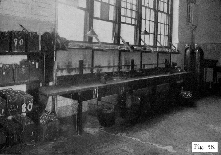
Fig. 38. Typical Work Room Showing Bench About 34 Inches High, Lead Burning Outfit, Hot Plates for Melting Sealing Compound and Hand Drill-Press for Drilling off Inter-Cell Connectors. |
There are some things, however, which are necessary, and the following lists are given to help the repairman select his equipment. The man with limited capital will be unable to buy a complete equipment at the start, but he should add to his equipment as fast as his earnings will permit. The repairman may be able to "get-by" with crude equipment when his business is very small, but to make his business grow he must absolutely have good equipment.The following list gives the various articles in the order of their importance. The first seven are absolutely necessary, even for the poorest beginner. The others are also essential, but may be bought as soon, as the money begins to come in. Some of the tools must also be bought before opening doors for business, such as the putty knife, screwdrivers, pliers, and so on. Each article, which requires explanation, is described in detail, beginning on page 100.
Equipment Which is Absolutely Necessary
1. Charging Outfit, such as a motor-generator set, rectifier, or charging resistance where direct current is available.2. Charging Bench and Accessories. With the charging bench must go the following:
- A syringe-hydrometer for measuring specific gravity of electrolyte, for drawing off electrolyte and for adding water to cells.
- A special battery thermometer for measuring temperature of electrolyte.
- A voltmeter to measure cell, battery, and cadmium voltages.
- An ammeter to measure charging current.
- A glass bottle for distilled water. Also one for electrolyte.
- A number of eighteen inch lengths of No. 12 flexible wire fitted with lead coated test clips, for connecting batteries in series while on charge.
3. Work bench with vise.
4. Sink or wash tank and water supply.
5. Lead-burning outfit. (This should properly be called a lead welding outfit, since it is used to melt lead parts so that they will be welded together.)
6. For handling sealing compound, the following are necessary.
- Stove.
- Pot in which compound is melted.
- An iron ladle for dipping up the melted compound.
- One or two old coffee pots for pouring compound.
7. Shelving or racks for batteries waiting to be repaired, batteries which have been repaired, rental batteries, new batteries, battery boxes, battery jars, battery plates, etc.
8. Bins for battery parts, such as covers, inter-cell connectors, plate straps, terminals, handles, vent plugs, hold down bolts, separator hold-downs, and so on.
Equipment Needed In Opening Batteries
9. A battery steamer for softening sealing- compound and making covers limp, for softening compound around defective jars which are to be removed, for softening jars which are to be set in a battery box, and so on.10. Putty knife to remove softened scaling compound.
11. One ratchet brace with set of wood bits or square shank drills of the following sizes: 3/8, 5/8, 3/4, 13/16, and 7/8 inch, for drilling off terminals and inter-cell connectors. A power drill press, or a portable electric drill will save time and labor in drilling off the terminals and connectors.
12. Center punch for marking terminals and connectors before drilling.
13. Ten inch screwdriver for prying off connectors and terminals which have been drilled. The screwdriver may, of course, be used on various other kinds of work also.
14. A ten-inch length of 3/4 inch angle iron to protect upper edge of case when prying off the connectors and terminals which have been drilled.
15. Two pair-, of standard combination pliers for lifting elements out of jars. A pair of six or eight inch gas pliers will also do for this work.
16. Machinist hammer. This is, of course, also used for other purposes.
17. Terminal tongs for removing taper lugs from terminals
18. Pair of long, fiat nosed pliers for pulling out separators and jars.
19. Open-end wrench for use in removing taper lugs from terminals.
Equipment for Lead Burning (Welding)
In addition to the lead burning- outfit, the following tools are needed:20. A plate burning rack for setting up plates which are to be burned to a plate strap.
21. A plumber's or tinner's triangular scraper for cleaning surfaces which are to be welded together. A pocketknife will do in a pinch.
22. Steel wire brush for cleaning surfaces which are to be -welded together. This may also be used for general cleaning of lead parts.
23. Coarse files, vixen, round, and flat, for filing lead parts.
24. Set of burning, collars to be used in burning inter-cell connectors to posts.
25. Moulds for casting sticks of burning lead. A pot for melting lead is needed with the mould, and mould compound is also needed.
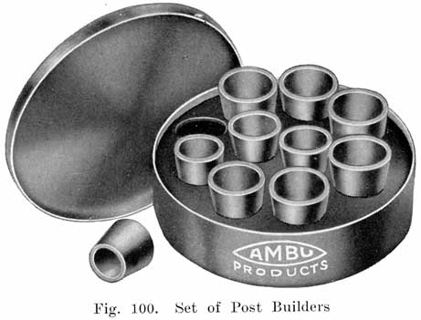
26. Set of post builders-moulds used for building up posts which have been drilled short in removing terminals and intercell connectors.
27. Pair of blue or smoked glasses to be worn when using lead burning outfit.
Equipment for General Work on Cell Connectors and Terminals
28. Set of moulds for casting inter-cell connectors, terminals, terminal screws, taper lugs, plate straps and posts, etc.29. Set of reamers to ream holes in terminals and connectors.
30. Set of hollow reamers for reducing posts.
31. Cans of asphaltum paint for painting cases. May also be used for acid-proofing work benches, floor, shelves, charging bench, and so on.32. Paint brushes, one wide and several narrow.
33. Battery turntable.
34. Several wood chisels of different sizes.
35. Small wood-plane for smoothing up top edges of case.
36. Large glazed earthenware jars of washing or baking soda solution for soaking cases to neutralize acid.
Tools and Equipment for General Work
37. One pair of large end cutting nippers for cutting connectors, posts, plate lugs, and so on.38. One pair of 8 inch side cutting pliers.
39. One pair of 8 inch diagonal cutting pliers.
40. Several screwdrivers.
41. Adjustable hacksaw frame with set of coarse blades.
42. Gasoline torch.
43. Soldering iron, solder and flux.
44. Separator cutter.
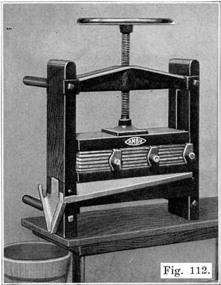
45. Plate press for pressing bulged, spongy lead of negative plates flush with surface of grids.
46. Battery carrier.
47. Battery truck.
48. Lead lined box for storing separators. A large glazed earthenware jar may be used for this purpose, and is much cheaper, although it will not hold as many separators, on account of its round shape, as the lead lined box.
49. Several old stew pans for boiling acid soaked terminals, connectors, covers, etc., in a solution of washing soda.
50. Set of metal lettering stamps, for stamping POS and NEG on battery terminals, repairman's initials, date battery was repaired, and nature of repairs, on inter-cell connectors.
51. Cadmium test set.
52. High rate discharge testers.
53. Pair of rubber gloves to protect hands when handling acid.
54. Rubber apron to protect clothing from acid.
55. Pair of rubber sleeve protectors.
56. Rubbers to protect shoes, or pair of low rubber boots.
57. Tags for tagging repair and rental batteries, batteries in storage, etc.
58. Pot of paraffine which may be heated, and paper tags dipped after date has been written on tag in pencil. A 60-watt lamp hung in the can may be used for heating the compound. In this way the tag is protected from the action of acid, and the writing on the tag cannot be rubbed off or made illegible.
59. A number of wooden boxes, about 12 inches long, 8 inches wide, and 4 inches deep, in which are placed terminals, inter-cell connectors, covers, vent plugs, etc., of batteries being repaired.
60. Several large glazed earthenware jars are convenient for waste acid, old separators, and general junk, which would otherwise litter up the shop.
Stock
61. A supply of spare parts, such as cases, jars, covers, plate straps, inter-cell connectors, plates, vent plugs, etc., should be kept.62. A supply of sealing compound is necessary.
63. A carboy of. pure acid, and carboys of 1.400 electrolyte ready for use should be on hand. A 16 oz. and a 32 or 64 oz. graduate are very useful in measuring out acid and water.
64. A ten gallon bottle of distilled water is necessary for use in making up electrolyte, for addition to cell electrolyte to bring electrolyte up to proper level, and so on. If you wish to distill water yourself, buy a water still.
65. A supply of pure vaseline is necessary for coating terminals to prevent corrosion.
Special Tools
Owing to special constructions used oil sonic of the standard makes of batteries, special tools are required, and such tools should be obtained if work is done oil these batteries. Some of these tools are as follows:
66. Special wrenches for turning sealing nuts on Exide batteries.
67. Two hollow reamers (post-freeing tools) for cutting lead seal around posts of Prest-O-Lite batteries. There are two sizes, large and small, see page 389.
68. Style "B" peening press for sealing posts of Prest-O-Lite batteries to covers, see page 390.
69. Pressure tongs for forcing lead collar oil posts of Vesta batteries, see page 415.
70. Special wrench for tightening sealing nut oil Titan batteries.
71. Special reamer for cutting sealing ring oil Universal batteries.
The list of special tools is not intended to be complete, and the repairman will probably find other special tools necessary from time to time. In any case, it is best to buy from the battery manufacturer such special tools as are necessary for the batteries that come in for repairs. It is sometimes possible to get along without the special tools, but time and labor will be saved by using them.
DESCRIPTIONS OF TOOLS AND EQUIPMENT NAMED IN FOREGOING LIST
Charging Equipment
A battery is charged by sending a direct current through it, this "charging" current entering the battery at, the positive terminal and passing out at the negative terminal. To send this current through the battery, a voltage of about 7.5 volts is applied to each battery.Two things are therefore necessary in charging a battery:,
1. We must have a source of direct current.2. The voltage impressed across each battery must be, about 2.5 per cell. The charging voltage across each six volt battery must therefore be 7.5, and for each twelve volt battery the charging voltage must be about 15 volts.
With the battery on the car, there are two general methods of charging, i. e., constant potential (voltage) and constant current. Generators having a constant voltage regulator have a constant voltage of about 7.5, the charging current depending upon the condition of the battery. A discharged battery thus receives a high charging current, this current gradually decreasing, or "tapering" as the battery becomes more fully charged. This system has the desirable characteristic that a discharged battery receives a heavy charging current, and a fully charged battery receives a small charging current. The time of charging is thereby decreased.
With a constant-current charging system, the generator current output is maintained at a certain value, regardless of the state of charge of the battery. The disadvantage of this system is that a fully charged battery is charged at as high a rate and in most cases at a higher rate than a discharged battery.
In the shop, either the constant-potential, or the constant-current system of charging may be used. Up to the present time, the constant current system has been used in the majority of shops. The equipment for constant current charging uses a lamp bank or rheostat to regulate the charging current where direct current is available, and a rectifier or motor-generator set where only alternating current is available. Recently, the Hobart Brothers Company of Troy, Ohio, has put on the market a constant potential motor-generator set which gives the same desirable "tapering" charge as does the constant voltage generator on the car. This set will be described later.
Where a 110-volt direct current supply is available, fifteen 6-volt batteries may be connected in series across the line without the use of any rheostat or lamp bank, only an ammeter being required in the circuit to indicate the charging current. The charging rate may be varied by cutting out some of the batteries, or connecting more batteries in the circuit. This method is feasible only where many batteries are charged, since not less than fifteen 6-volt batteries may be charged at one time.
Using Lamp Banks, or Rheostats
Figures 39 and 40 show the wiring for a "bank" of twenty 100-watt lamps for battery charging from a 110 volt line. Figure 39 shows the wiring to be used when the positive side of the line is grounded, while Figure 40 shows the wiring to be used when the negative side of the line is grounded. In either case, the "live" wire connects to the lamp bank. The purpose of this is to eliminate the possibility of a short-circuit if any part of the charging line beyond the lamp bank is accidentally grounded.
![]()
Figures 41 and 42 show the wiring of two charging rheostats which may be used instead of the lamp banks shown in Figures 39 and 40. In these two rheostats the live wire is connected to the rheostat resistances in order to prevent short-circuits by grounding any part of the circuit beyond the rheostats. These rheostats may be bought ready for use, and should not be "homemade." The wiring as shown in Figures 41 and 42 is probably not the same as will be found on a rheostat which may be bought, but when installing a rheostat, the wiring should be examined to make sure that the "live" wire is connected to the rheostat resistance and does not connect directly to the charging circuit. If necessary, change the wiring to agree with Figures 41 and 42.Figures 43 and 44 show the wiring of the charging circuits. In Figure 43 each battery has a double pole, double throw knife switch. This is probably the better layout, since any battery may be connected in the circuit by throwing down the knife switch, and any battery may be cut out by throwing the switch up. With this wiring layout, any number of batteries from one to ten may be cut-in by means of the switches. Thus, to charge five batteries, switches 1 to 5 are thrown down, and switches 5 to 10 are thrown up, thereby short-circuiting them.
Figure 44 shows a ten-battery charging circuit. on which the batteries are connected in series by means of jumpers fitted with lead coated test clips, as shown. This layout is not as convenient as that shown in Figure 43, but is less expensive.
Where no direct current supply is available, a motor-generator or a rectifier must be installed. The motor-generator is more expensive than a rectifier, but is preferred by some service stations because it is extremely flexible as to voltage and current, is easily operated, is free from complications, and has no delicate parts to cause trouble. |
|
Except in very large service stations, a 40 volt generator is preferable. It requires approximately 2.5 volts per cell to overcome the voltage of a battery in order to charge it, and hence the 40 volt generator has a voltage sufficient to charge 15 cells in series on one charging line. Five 6 volt batteries may therefore be charged at one time on each line. With a charging rate of 10 amperes, each charging line will require 10 times 40, or 400 watts. The size of the generator will depend on the number of charging lines desired. With 10 amperes charging current per line, the capacity of the generator required will be equal to 400 watts multiplied by the number of charging lines. One charging line will need a 400 watt outfit. For two charging lines 800 watts are required. Each charging line is generally provided with a separate rheostat so that its charging rate may be adjusted to any desired value. This is an important feature, as it is wrong to charge all batteries at the same rate, and with separate rheostats the current on each line may be adjusted to the correct value for the batteries connected to that line. Any number of batteries up to the maximum may be charged on each line.
In choosing a charging outfit, it is important not to get one which is too large, as the outfit will operate at a loss when running under a minimum load. It is equally important not to get one which is too small, as it will not be able to take care of the batteries fast enough, and there will be a "waiting list" of batteries which cannot be charged until others are taken off charge. This will prevent the giving of good service. Buy an outfit that will care for your needs in the future, and also operate economically at the present time. Most men going into the battery business make the mistake of underestimating their needs, and getting equipment which must soon be discarded because of lack of capacity.
The manufacturers each make a number of sizes, and the one which will best fill the requirements should be chosen. In selecting an outfit the manufacturer's distributor or dealer should be consulted in deciding what size outfit to obtain. The particular outfit will depend on the voltage and frequency of the alternating current power circuits, the maximum charging current desired (10 amperes per line is ample), and the greatest number of batteries to be charged at one time.
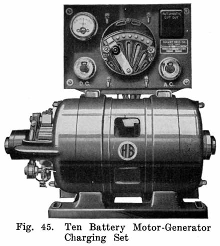
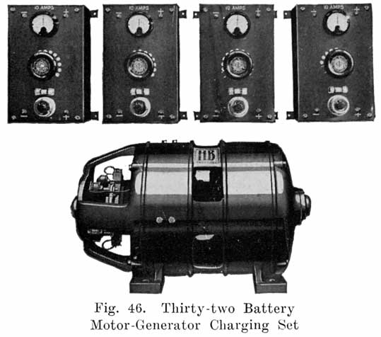
For the beginner, a 500 watt ten battery outfit, as shown in Fig. 45, is suitable. For the medium sized garage that specializes in battery charging, or for the small battery service station, a one kilowatt outfit is most satisfactory. Two charging panels are generally furnished with this outfit, and two charging lines may thus be used. This is an important feature, as one line may be used in starting a charge at 10 amperes, and the other for charging the batteries, that have begun to gas, at a reduced rate. Fig. 46 shows a 2 K. W. four-circuit, 32 battery motor-generator set. Each circuit is provided with a separate rheostat and ammeter. The two terminals near the top of each rheostat are connected to one charging circuit. The two terminals near the lower end of each rheostat are connected to the generator.
The 2 kilowatt set is suitable for a city garage, or a battery service station in a medium sized town. A beginner should not purchase this large set, unless the set can be operated at at least one-fourth capacity continuously. As a service station grows, a 5 kilowatt set may be needed. The 1, 2 and 5 kilowatt sets should not be used on anything but city power lines. Single phase, or lighting lines are not satisfactory for handling these sets.
A few suggestions on Motor-Generator Sets
1. Installation. Set the motor-generator on as firm a foundation as possible. A good plan is to bolt it to a heavy bench, in which position it is easily inspected and adjusted, and is also less likely to be hit by acid spray, water, etc.Set the motor-generator at some distance from the batteries so that acid spray and fumes will not reach it. Sulphuric acid will attack any metal and if you are not careful, your motor-generator may be damaged seriously. The best plan is to have the motor generator set outside of the charging room, so as to have a wall or partition between the motor-generator and the batteries. The charging panels may be placed as near the batteries as necessary for convenience, but should not be mounted above the batteries. Figure 47 shows a convenient layout of motor-generator, charging panels, and charging benches. Note that the junipers used in connecting the batteries together are run through the upper holes of the wire porcelain insulating cleats, the lower hole of each insulator supporting the wire from the charging panel which runs to the end of the bench.
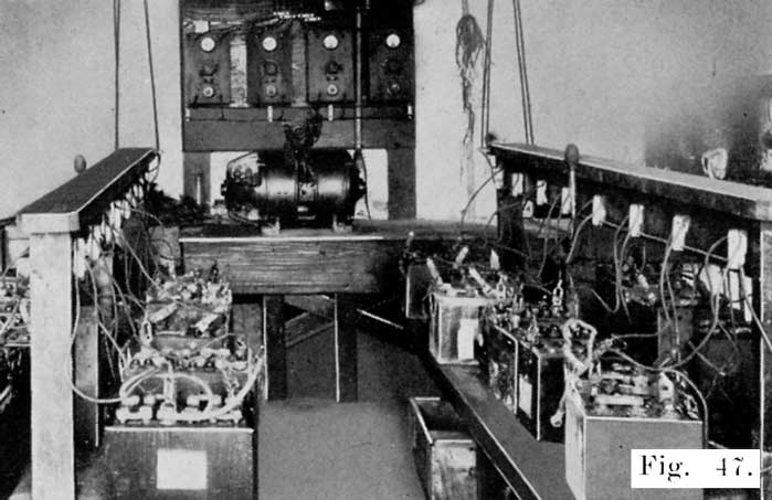
Fig. 47. Convenient Arrangement of Motor-Generator, Charging Panels, and Charging Benches
Instructions for the wiring connections to the power lines generally come with each outfit, and they should be followed carefully. Fuses in both the motor and generator circuits are especially important, as they protect the machines from damage due to overloads, grounds, or short-circuits. The generator must be driven in the proper direction or the generator will not build up. The rotation of a three-phase motor may be reversed by reversing, and Charging Benches any two of the cables. To reverse a two-phase motor, reverse the cables of either phase. Before putting a motor-generator set into operation, be sure to check all connections to make sure that everything checks with the instructions furnished by the manufacturer.
Operating the Charging Circuits
A generator operates most efficiently when delivering its rated output. Therefore, keep the generator as fully loaded as possible at all times. When you do not have enough batteries to run the generator at full load, run each charging circuit at full load, and use as few circuits as possible. This will reduce your power bill, since there is a loss of power in the rheostat of each charging circuit, this loss being the greatest when only one battery is on the circuit, and a minimum when the circuit is fully loaded.With several charging circuits, it is also possible to put batteries which are in the same condition on one circuit and adjust the charging rate to the most suitable value. Thus, badly sulphated batteries, which must be charged at a low rate, may be put on the same circuit, while batteries which have had only a normal discharge may be put oil another circuit and charged at a higher rate. As each battery becomes almost fully charged, it may be removed from the circuit and put on another circuit and the charge completed at the finishing rate. This is a good practice, since some batteries will begin to gas sooner than others, and if the charging rate is not reduced, the batteries which have begun to gas will have active material blown out by the continued gassing. A careful study of such points will lead to a considerable saving in power costs.
A. Machine will not build up or generate. This may be due to:
- Machine rotating in wrong direction.
- Brushes not making good contact. Clean commutator with fine sandpaper"
- Wrong connections of field rheostat-check connections with diagram.
- Open circuit in field rheostat. See if machine will build up with field rheostat cut out.
B. Excessive heating of the commutator. This may be due to:
- Overload-Check your load and compare it with nameplate reading. Add the total amperes on all the panels and see that it does not exceed the ampere reading on the nameplate.
- Wrong setting of the brush rocker arm. This causes sparking, which soon will cause excessive heating.
- Rough commutator. This will cause the brushes to chatter, be noisy and spark. Caused many times by allowing copper to accumulate on the bottom of the brushes.
- Insufficient pressure on brushes, resulting in sparking. This may be due to brushes wearing down to the point where the brush lead screw rests on the brush holder.
- Dirt and grease accumulating between the brush and brush holder causing brush to stick;brush must always move freely in the holder.
- Brush holder may have come loose, causing it to slip back, relieving brush press-Lire.
- Brush spring may have become loosened, releasing the tension.
- Watch commutator carefully and keep it in the best of condition. There will not be excessive heating without sparking. Excessive sparking may raise the temperature so high as to cause throwing of solder. You can avoid all this by taking proper care of the commutator.
C. Ammeters on Panels Read Reverse: This is caused by improperly connecting up batteries, which has reversed the polarity of the generator. This generally does no harm, since in most cases the batteries will automatically reverse the polarity of the generator. Generally the condition may be remedied by stopping the machine, reversing the batteries and starting the machine again. If this is unsuccessful raise the brushes on the machine. Connect five or six batteries in series in the correct way to one panel, while the machine is not in operation. Turn on the panel switch. When the machine is started, it will then build up in the right direction. If it does not do so, repeat the above, using a larger number of batteries.
D. Machine Refuses to Start. If there is a humming noise when you try to start the motor, and the outfit does not start, one of the fuses needs replacing. The outfit will hum only on two or three phase current. Never leave the power turned on with any of the fuses out.
In the Constant-Potential system of battery charging, the charging voltage is adjusted to about 7.5, and is held constant throughout the charge. With this system a discharged battery receives a heavy current when it is put on charge. This current gradually decreases as the battery charges, due to the increasing battery voltage, which opposes, or "bucks" the charging voltage, and reduces the voltage which is effective in sending current through the batteries. Such a charge is called "tapering" charge because the charging current gradually decreases, or "tapers" off.The principle of a "tapering" charge is, of course, that a discharged battery may safely be charged at a higher rate than one which is only partly discharged, because there is more lead sulphate in the discharged battery which the action of the current changes back to active material. As the battery charges, the amount of lead sulphate decreases and since there is less sulphate for the current to act upon, the charging rate should be reduced gradually. If this is not done, excessive gassing will occur, resulting in active material being blown from the grids.
A battery which has been badly sulphated, is of course, in a discharged condition, but is not, of course, able to absorb a heavy charging rate, and in handling such batteries on a constant potential system, care must be taken that the charging rate is low. Another precaution to be observed in all constant potential charging is to watch the temperature of batteries while they are drawing a heavy charging current. A battery which gasses soon after it is put oil charge, and while still in a discharged condition, should be taken off the line, or the charging line voltage reduced. With constant potential charging, as with constant current charging, the two things to watch are temperature and gassing. Any charging rate which does not cause an excessive temperature or early gassing is safe, and conversely any charging rate which causes an excessive battery temperature, or causes gassing while the battery is still less than three-fourths charged, is too high.
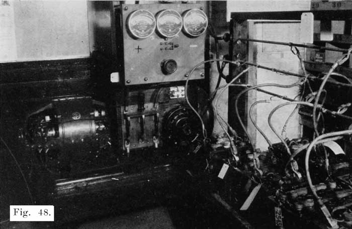
Fig. 48. Hobart Bros. Co. 3 K. W. Constant Potential Motor-Generator Charging Set
The Constant-Potential Charging Set manufactured by the Hobart Bros. Co., consists of a 3 K.W. generator rated at 7.5 volts, and 400 amperes. This generator is direct connected to a 5 H.P. motor, both machines being mounted oil the same base plate. Figure 48 shows this outfit. Note that for the charging line there are three bus-bars to which the batteries are connected. Twelve volt batteries are connected across the two outside bus-bars, while six volt batteries are connected between the center bus-bar and one of the outer ones.
All rectifiers using ail are operate oil the principle
that current call pass through them in one direction
only, due to the great resistance offered to the flow of
current in the opposite direction. It is, of course, not
necessary to use mercury vapor for the are. Some
rectifiers operate on another principle. Examples of such
rectifiers are the Tungar made by the General Electric
Co., and the Reetigon, made by the Westinghouse Electric
and Manufacturing Co. The Tungar Rectifier is used
extensively and will therefore be described in
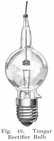
detail. The essential parts of a Tungar Rectifier are: A bulb,
transformer, reactance, and the enclosing case and
equipment. The bulb is the most important of these parts, since
it does the rectifying. It is a sort of check valve that
permits current to flow through the charging circuit in
one direction only. In appearance the bulb, see Figure
49, resembles somewhat an ordinary incandescent bulb. In
the bulb is a short tungsten filament wound in the form
of a tight spiral, and supported between two lead-in
wires. Close to the filament is a graphite disk which
serves as one of the electrodes. Figure 50 shows the
operating principle of the Tungar. "B" is the bulb,
containing the filament "F" and the graphite electrode
"A." To serve as a rectifier the bulb filament "F" must
be heated, this being done by the transformer "T." The
battery is connected as shown, the positive terminal
directly to one side- of the alternating current supply,
and the negative terminal to the graphite electrode
"A."
To understand the action which takes place, assume an instant when line wire C is positive. The current then flows through the battery, through the rheostat and to the graphite electrode. The current then flows through the are to the filament and to the negative side of the line, as indicated by the arrows.During the next half cycle -when line wire D is positive, and C is negative, current tends to flow through the bulb from the filament to the graphite, but as the resistance offered to the flow of current in this direction is very high, no current will flow through the bulb and consequently none through the battery.
![]()
![]()
The rectifier shown in Figure 50 is a "half-wave" rectifier. That is, only one-half of each alternating current wave passes through it to the battery. If two bulbs are used, as shown ill Figure 51, each half of the alternating current wave is used in charging the battery. To trace the current through this rectifier assume an instant when line wire C is positive. Current will then flow to the graphite electrode of tube A, through the secondary winding of the transformer S to the center tap, through the rheostat, to the positive battery terminal, through the battery to the center of the primary transformer winding P, and through part of the primary winding to D. When D is positive, current will flow through tube B from the graphite electrode to the filament, to the center of transformer winding S, through the rheostat and battery to the center of transformer winding P, and through part of this winding to line wire C. In the actual rectifiers the rheostat shown in Figures 50 and 51 are not used, regulation being obtained entirely by means of other windings.From the foregoing description it will be seen that if the alternating current supply should fail, the batteries cannot discharge into the line, because in order to do so, they would have to heat up the filament and send current through the bulb from the filament to the graphite electrode. This the batteries cannot do, because the connections are such that the battery cannot send a current through the complete filament circuit and because, even if the batteries could heat the filament they could not send a current from the filament to the graphite, since current cannot flow in this direction.
As soon as the alternating line is made alive again, the batteries will automatically start charging again. For these reasons night charging with the Tungar is entirely feasible, and no attendant is required to watch the batteries during the night. The Tungar Rectifier is made in the following sizes:
Catalogue No. 195529
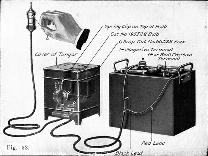
Fig. 52. The Two Ampere Tungar Rectifier
This is the smallest Tungar made. Figure 52 shows the complete rectifier. Figure 53 shows the internal wiring. This Tungar will charge a 6 volt battery at two amperes, a 12 volt battery at one ampere and eight cells at 0.75 ampere. It is suitable for charging a lighting battery, or for a quick charge of a motorcycle or ignition battery. It will also give a fairly good charge over night to a starting battery. Another use for this rectifier is to connect it to a run-down starting battery to prevent it from freezing over night. Of course, a battery should not be allowed to run down during cold weather, but if by chance a battery does run down, this Tungar will prevent it from freezing during the night. |
|
Catalogue No. 219865
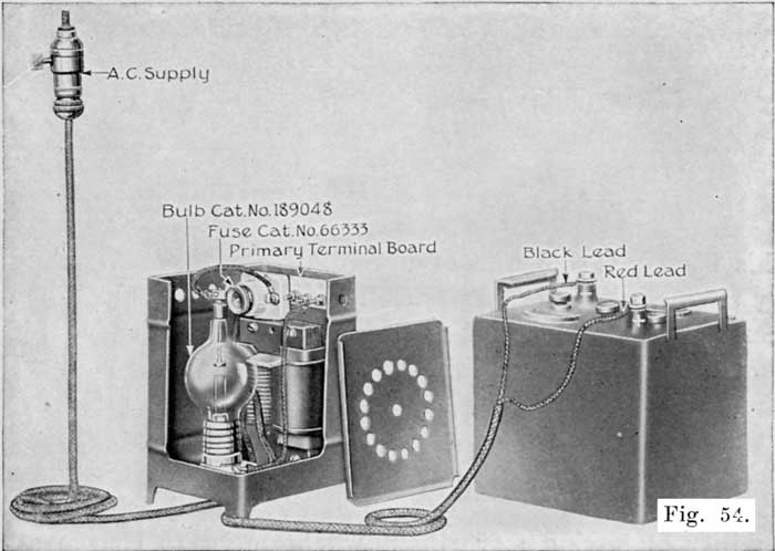
Fig. 54. The One Battery Tungar Rectifier
This Tungar will charge a 6 volt battery at five amperes, or a 12 volt battery at three amperes. Figure 54 shows this Tungar, with part of the casing cut away to show the internal parts.To take care of variations in' the voltage of the alternating current supply from 100 to 130, a set of connections is provided which are numbered 105, 115, and 125. For most supply voltages, the 115 volt tap is used, for lower voltage the 105 volt tap is used, and for higher voltage the 125 volt tap is used. This Tungar is designed for 60 cycle circuits, but on special order it may be obtained for operation on other frequencies.
This Tungar is most suitable for a car owner, is satisfactory for charging a radio "A" battery, and a six volt starting and lighting battery at one time.
Catalogue No. 195530
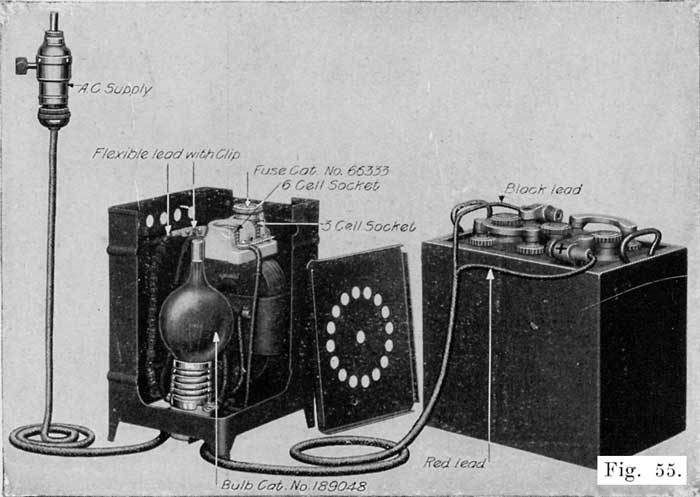
Fig. 55. The Two Battery Tungar Rectifier
This Tungar is shown in Figure 55, with part of the casing cut away to show the internal parts. It was formerly sold to the car owner, but the one battery Tungar is now recommended for the use of the car owner. The two-battery Tungar is therefore recommended for the very small service station, or for department stores for taking care of one or two batteries. The four battery Tungar, which is the next one described, is recommended in preference to the two-battery outfit where there is the slightest possibility of having more than two batteries to charge at one time.The two-battery rectifier will charge two 6-volt batteries, or one 12-volt battery at six amperes, or one 18-volt battery at three amperes. It has a double-pole fuse block mounted on the auto transformer core, which has one fuse plug only. Figure 55 shows the fuse plug in the position for charging a 6-volt battery. When it is desired to charge a 12-volt battery or an 18-volt battery, the fuse is removed from the first receptacle and is screwed into the second receptacle.

Fig. 56. The Four Battery Tungar Rectifier Complete
The two-battery rectifier is designed to operate on a 115-volt, 60-cycle line, but oil special order may be obtained for operation on 25-30, 40-50, and 125-133 cycle lines.
Catalogue No. 193191
This Tungar is shown complete in Figure 56. In Figure 57 the top has been raised to show the internal parts. Figure 58 gives the internal wiring connections for a four battery Tungar designed for operation on a 115 volt line.The four battery Tungar will charge from one to four 6 volt batteries at 5 amperes or less. It is designed especially for garages having very few batteries to charge. These garages generally charge their boarders batteries rather than send them to a service station, and seldom have more than four batteries to charge at one time. The four battery Tungar is also suitable for the use of car dealers who wish to keep the batteries on their cars in good shape, and is convenient for preparing for service batteries as they come from the car manufacturer.
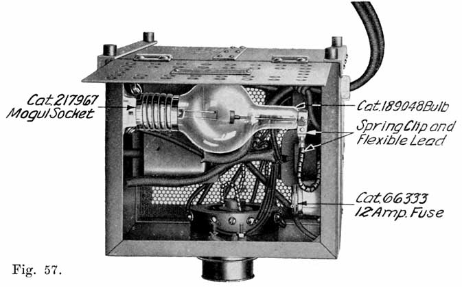
Fig. 57. The Four Battery Tungar Rectifier, with Top Raised to Show Internal Parts.
The four battery Tungar is designed for operation. on a 60-cycle line at 115 or 230 volts. On special order this Tungar may be obtained for operation on other frequencies.
Catalogue No. 179492
This is the Tungar which is most popular in the service stations, since it meets the charging requirements of the average shop better than the smaller Tungars. It will charge from one to ten 6 volt batteries, or the equivalent at six amperes or less. Where more than ten batteries are generally to be charged at one time, two or more of the ten battery Tungars should be used. Large service stations use as many as ten of these Tungars.
The efficiency of the ten battery Tungar at full load is approximately 75 per cent, which compares favorably with that of a mercury-are rectifier, or motor-generator of the same size. This makes the ten battery Tungar a very desirable piece of apparatus for the service station.
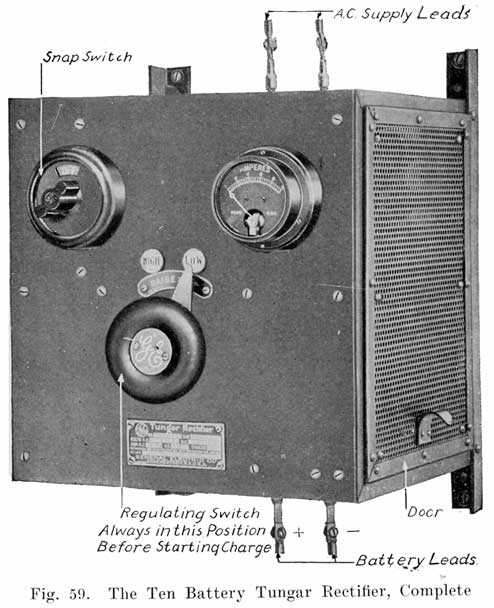
Figure 59 shows the complete ten battery Tungar, Figure 60 gives a side view without the door to show the internal parts.
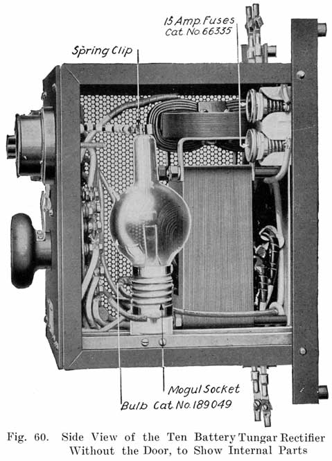
Figure 61 shows the internal connections for use on a 115-volt A.C. line and Figure 62 the internal connections for use on a 230-volt line. This Tungar is made for a 60-cycle circuit, 25-30, 40-50, and 125-133 cycle circuits.
___
![]()
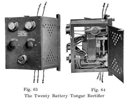
Catalogue No. 221514
This Tungar will charge ten 6-volt batteries at 12 amperes, or twenty 6-volt batteries at six amperes. Figure 63 shows the complete rectifier, and Figure 64 shows the rectifier with the side door open to show the internal parts. This rectifier will do the work of two of the ten battery Tungars. It is designed for operation on 60 cycles, 230-volts. On special order it may be obtained for operation on 115 volts and also for other frequencies.The twenty battery Tungar uses two bulbs, each of which is the same as that used in the ten battery Tungar, and has two charging circuits, having an ammeter and regulating switch for each circuit. One snap switch connects both circuits to the supply circuit. The two charging circuits are regulated independently. For example, one circuit may be regulated to three amperes while the other circuit is delivering six amperes. It is also possible, by a system of connections to charge the equivalent of three circuits. For instance, five batteries could be charged at six amperes, five batteries at four amperes, and five batteries at ten amperes. Other corresponding combinations are possible also.
General Instructions and Information on Tungars
Life of Tungar Bulbs. The life of the Tungar Bulb is rated at 600 to 800 hours, but actually a bulb will give service for 1,200 to 3,000 hours if the user is careful not to overload the bulb by operating it at more than the rated current.
Instructions. Complete instructions are furnished with each Tungar outfit, the following being those for the ten battery Tungar.
A Tungar should., be installed in a clean, dry place -in order to keep the apparatus free from dirt and moisture. To avoid acid fumes, do not place the Tungar directly over the batteries. These precautions will prevent corrosion of the metal parts and liability of poor contacts.Fasten the Tungar to a wall by four screws, if the wall is of wood, or by four expansion bolts if it is made of brick or concrete.
Though the electrical connections of the outfit are very simple, it is advisable (when installing the apparatus) to employ an experienced wireman familiar -with local requirements regarding wiring.
The two wires extending from the top of the Tungar should be connected to the alternating current supply of the same voltage and frequency, as stamped on the name plate attached to the front panel. These connections should be not less than No. 12 B. & S. gauge wire and should be firmly soldered to the copper lugs.External fuses are recommended for the alternating-current circuit, as follows:
With 115-volt line use 15-ampere capacity fuses.With 230-volt line use 10 ampere capacity fuses.
One of the bulbs (Cat. No. 189049) should now be firmly screwed into its socket. Squeeze the spring clip attached to the beaded cable and slip this clip over the wire protruding from the top of the bulb. Do not bend the wire.
In making battery connections have the snap-switch in the "Off" position.The two wires extending from the bottom of the Tungar should be connected to the batteries. The wire on the left, facing the front panel, is marked + (positive) and the other wire - (negative). The positive wire should be connected to the positive terminal of the battery and the negative wire to the negative terminal.
The two flexible battery cables are sometimes connected directly to the two wires projecting from the bottom of the Tungar. These cables should be securely cleated to the wall about six inches below the outfit. This arrangement will relieve the strain on the Tungar wires when cables are changed to different batteries.
When two or more batteries are to be charged, they should be connected in series. The positive wire of the Tungar should be connected to the positive terminal of battery No. 1, the negative terminal of this battery of the positive terminal of battery No. 2, the negative terminal of battery No. 2 to the positive terminal of battery No. 3, and so on, according to the number of batteries in circuit. Finally the negative terminal of the last battery should be connected to the negative wire from the Tungar.
Reverse connections on one battery is likely to damage the plates; and reverse connections oil all the batteries will blow one or more fuses.
A Tungar is operated by means of a snap-switch in the upper left-hand corner and a regulating switch in the center. Before starting the apparatus, the regulating switch should be in the "low" position.The Tungar is now ready to operate. Turn the snap-switch to the right to the "On" position, and the bulb will light. Then turn the regulating switch slowly to the right, and, as soon as the batteries commence to charge, the needle on the ammeter will indicate the charging current. This current may be adjusted to whatever value is desired within the limits of the Tungar. The normal charging rate is six amperes, but a current of as high as seven amperes may be obtained without greatly reducing the life of the bulb. Higher charging rates reduce its life to a considerable extent. Lower rates than normal (six amperes) will increase the life of the bulb.
Turn the snap-switch to the "Off" position when the charging of one battery or of all the batteries is completed; or when it is desired to add more batteries to the line.
The Tungar should be operated only by the snap-switch and not by any other external switch in either line or battery circuits.
When the snap-switch is turned, the batteries will be disconnected from the supply line, and then they may be handled without danger of shock.
Immediately after turning the snap-switch, move the regulating handle back to the "Low" position. This prevents any damage to the bulb from the dial switch being in an improper position for the number of batteries next charged.
If on turning on the alternating-current switch the bulb does not glow:
- See whether the alternating-current supply is on.
- Examine the supply line fuses. If these are blown, or are defective, replace them with 15 ampere fuses for a 115-volt line or with 10-ampere fuses for a 220-volt line.
- Make sure that the bulb is screwed well into the socket.
- Examine the contacts inside the socket. If they are tarnished or dirty, clean them with sandpaper.
- Try a new bulb, Cat. No. 189049. The old bulb may be defective.
If the bulb lights but no current shows on the ammeter:
- Examine the connections to the batteries, and also the connections between them. Most troubles are caused by imperfect battery connections.
- Examine the fuses inside the case. If these are blown or are defective, replace them with 15 ampere fuses, Cat. No. 6335.
- See that the clip is on the wire of the bulb.
- The bulb may have a slow leak and not rectify. Try a new bulb, Cat. No. 189049.
- Have the switch arm make good contact on the regulating switch.
If the current on the ammeter is high and cannot be reduced:
- The ammeter pointer may be sticking; tap it lightly with the hand. The ammeter will not indicate the current correctly if the pointer is not on the zero line when the Tungar is not operating. The pointer may be easily reset by turning slightly the screw on the lower part of the instrument.
- Be sure that the batteries are not connected with reversed polarity.
- The. alternating-current supply may be abnormally high. If only one three-cell battery is being charged, and the alternating-current supply is slightly high, then the current on the ammeter may be high. The simplest remedy is to connect in another battery or a small amount of resistance.
A spare bulb should always be kept on hand and should be tested for at least one complete charge before being placed in reserve. All Tungar bulbs are made as nearly perfect as possible, but occasionally one is damaged in shipment. It may look perfect and yet not operate. For this reason all bulbs should be tried out on receipt. If any bulb is found defective, the tag which accompanies it should be filled out, and bulb and tag should be returned to your dealer or to the nearest office of the General Electric Company, transportation prepaid.
Tungar Rectifiers
(The following columns omitted: Catalog Numbers, Dimensions, Net Weight and Shipping Weight).
|
Name |
No. 6V Bats. |
No. 12V Bats. |
D.C Amps |
D.C. Volts |
A.C. Volts |
Freq. |
|
2 Amp. Tungar |
1 (2 amps.) |
1 (1 amps.) |
1-2 |
7.5-15 |
115 |
60 |
|
2 Amp. Tungar |
1 (2 amps.) |
1 (1 amps.) |
1-2 |
7.5-15 |
115 |
40-50 |
|
2 Amp. Tungar |
1 (2 amps.) |
1 (1 amps.) |
1-2 |
7.5-15 |
115 |
25-30 |
|
2 Amp. Tungar |
1 (2 amps.) |
1 (1 amps.) |
1-2 |
7.5-15 |
115 |
125-133 |
|
1 Battery Tungar |
1 (5 amps.) |
1 (3 amps.) |
1-5 |
7.5-15 |
115 |
60 |
|
2 Battery Tungar |
2 (6 amps.) |
1 (6 amps.) |
1-6 |
7.5-15 |
115 |
60 |
|
2 Battery Tungar |
2 (6 amps.) |
1 (6 amps.) |
1-6 |
7.5-15 |
115 |
40-50 |
|
2 Battery Tungar |
2 (6 amps.) |
1 (6 amps.) |
1-6 |
7.5-15 |
115 |
25-30 |
|
2 Battery Tungar |
2 (6 amps.) |
1 (6 amps.) |
1-6 |
7.5-15 |
115 |
125-130 |
|
4 Battery Tungar |
4 (5 amps.) |
2 (5 amps.) |
1-5 |
7.5-30 |
115 |
60 |
|
4 Battery Tungar |
4 (5 amps.) |
2 (5 amps.) |
1-5 |
7.5-30 |
115 |
40-50 |
|
4 Battery Tungar |
4 (5 amps.) |
2 (5 amps.) |
1-5 |
7.5-30 |
115 |
25-30 |
|
4 Battery Tungar |
4 (5 amps.) |
2 (5 amps.) |
1-5 |
7.5-30 |
115 |
125-133 |
|
4 Battery Tungar |
4 (5 amps.) |
2 (5 amps.) |
1-5 |
7.5-30 |
230 |
60 |
|
4 Battery Tungar |
4 (5 amps.) |
2 (5 amps.) |
1-5 |
7.5-30 |
230 |
40-50 |
|
10 Battery Tungar |
10 |
5 |
1-6 |
7.5-75 |
115 |
60 |
|
10 Battery Tungar |
10 |
5 |
1-6 |
7.5-75 |
115 |
40-50 |
|
10 Battery Tungar |
10 |
5 |
1-6 |
7.5-75 |
115 |
25-30 |
|
10 Battery Tungar |
10 |
5 |
1-6 |
7.5-75 |
115 |
125-133 |
|
10 Battery Tungar |
10 |
5 |
1-6 |
7.5-75 |
230 |
60 |
|
10 Battery Tungar |
10 |
5 |
1-6 |
7.5-75 |
230 |
40-50 |
|
20 Battery Tungar |
10 (12A.) 20 (6A.) |
10 (6A.) |
1-12 |
7.5-75 |
230 |
60 |
|
20 Battery Tungar |
10 (12A.) 20 (6A.) |
10 (6A.) |
1-12 |
7.5-75 |
230 |
40-50 |
|
20 Battery Tungar |
10 (12A.) 20 (6A.) |
10 (6A.) |
1-12 |
7.5-75 |
230 |
25-30 |
|
Bulb (all 4 Amp. Tung.) |
,,,,,,,, |
,,,,,,,, |
,,,,,,,, |
,,,,,,,, |
,,,,,,,, |
,,,,,,,, |
|
Bulb (all 10 and 12 Amp. Tung.) |
,,,,,,,, |
,,,,,,,, |
,,,,,,,, |
,,,,,,,, |
,,,,,,,, |
,,,,,,,, |
|
Bulb (all 2 Amp. Tung.) |
,,,,,,,, |
,,,,,,,, |
,,,,,,,, |
,,,,,,,, |
,,,,,,,, |
,,,,,,,, |
|
Bulb (all 1-2 Bat. Tung.) |
,,,,,,,, |
,,,,,,,, |
,,,,,,,, |
,,,,,,,, |
,,,,,,,, |
,,,,,,,, |
The operation of the mercury are rectifier depends upon the fact that a tube containing mercury vapor under a low pressure and provided with two electrodes, one of mercury and the other of some other conductor, offers a very high resistance to a current tending to pass through the tube from the mercury electrode to the other electrode, but offers a very low resistance to a current tending to pass through the tube in the opposite direction. Current passes from the metallic electrode to the mercury electrode through an are of mercury vapor which is established in the tube by tilting it so the mercury bridges the gap between the mercury and an auxiliary electrode just for an instant.The absence of moving parts to got out of order is an advantage possessed by this rectifier over the motor-generator. The charging current from the rectifier cannot, however, be reduced to as low a value as with the motor-generator, and this is a disadvantage. This rectifier is therefore more suitable for larger shops, especially where electric truck and pleasure cars are charged.
Mechanical rectifiers have a vibrating armature which opens and closes the charging circuit. The circuit is closed during one half of each alternating current cycle, and open during the next half cycle. The circuit is thus closed as long as the alternating current is flowing in the proper direction to charge the battery, and is open as long as the alternating current is flowing in the reverse direction. These rectifiers therefore charge the battery during half the time the battery is on charge, this also being the case in some of the are rectifiers.The desired action is secured by a combination of a permanent magnet and an electromagnet which is connected to the alternating current supply. During half of the alternating current cycle, the alternating current flowing through the winding of the electromagnet magnetizes the electromagnet so that it strengthens the magnetism of the permanent magnet, thus causing the vibrator arm to be drawn against the magnet. The vibrator arm carries a contact which touches a stationary contact point when the arm is drawn against the magnet, thus closing the charging circuit.
During the next half of the alternating current cycle, or wave, the current through the electromagnet coil is reversed, and the magnetism of the electromagnet then weakens the magnetism of the permanent magnet, and the vibrator arm is drawn away from the magnet and the charging circuit is thus opened. During the next half of the alternating current cycle the vibrator arm is again drawn against the magnet, and so on, the contact points being closed and opened during half of each alternating current cycle.
Mechanical rectifiers are operated from the secondary windings of transformers which reduce the voltage of the alternating current line to the voltage desired for charging. Each rectifier unit may have its own complete transformer, or one large transformer may operate a number of rectifier units by having its secondary, or low tension winding divided into a number of sections, each of which operates one rectifier.
The advantages of the mechanical rectifier are its simplicity, cheapness and portability. This rectifier also has the advantage of opening the charging circuit when the alternating current supply fails, and starting again automatically when the line is made alive again. Any desired number of independent units, each having its own charging line, may be used. The charging current generally has a maximum value of 6 amperes. Each rectifier unit is generally designed to charge only one or two six volt batteries at one time.
This is a unique rectifier, in which the alternating current is rectified by being sent through a commutator which is rotated by a small alternating current motor, similar to the way the alternating current generated in the armature of a direct current generator is rectified in the commutator of the machine. The Stahl rectifier supplies the alternating current from a transformer instead of generating it as is done in a direct current generator. Brushes which bear on the commutator lead to the charging circuit.The Stahl rectifier is suitable for the larger service stations. It gives an interrupted direct current. It is simple' in construction and operation, and is free of delicate parts.
Other Charging Equipment
If there is no electric lighting in the shop, it will be necessary to install a generator and a gas, gasoline, or steam engine, or a waterwheel to drive it. A 10 battery belt driven generator may be used in such a shop, and may also, of course, be used with a separate motor. The generator should, of course, be a direct current machine. The size of the generator will depend upon the average number of batteries to be charged, and the amount of money available. Any of the large electrical manufacturers or supply houses will give any information -necessary for the selection of the type and size of the outfit required.If an old automobile engine, and radiator, gas tank, etc., are on hand, they can be suitably mounted so as to drive the generator.
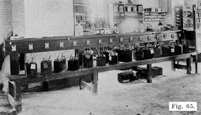
Fig. 65. Charging Bench with D.P.D.T. Switch for Each Battery
Figures 47 and 65 show charging benches in operation. Note that they are made of heavy stock, which is of course necessary on account of the weight of the batteries. The top of the charging bench should be low, to eliminate as much lifting of batteries as possible. Figure 66 is a working drawing of the bench illustrated in Figure 65. Note the elevated shelf extending down the center. This is convenient for holding water bottle, acid pitcher, hydrometer. Note also the strip "D" on this shelf, with the voltmeter hung from an iron bracket. With this arrangement the meter may be moved to any battery for voltage, cadmium, and high rate discharge readings. It also has the advantage of keeping the volt meter in a convenient and safe place, where it is not liable to have acid spilled on it, or to be damaged by rough handling. In building the bench shown in Figure 66, give each part a coat of asphaltum paint before assembling. After assembling the bench give it two more coats of asphaltum paint.
Figures 67, 68, 69 and 70 show the working plans for other charging benches or tables. The repairman should choose the one which he considers most suitable for his shop. In wiring these benches, the elevated shelf shown in Figure 66 may be added and the double pole, double throw switches used. Instead of these switches, the jumpers shown on the benches illustrated in Figure 47 may be used. If this is done, the elevated shelf should also be installed, as it is a great convenience for the hydrometer, voltmeter, and so on, as already described.As for the hydrometer, thermometer. etc., which were listed on page 96 as essential accessories of a charging bench, the Exide vehicle type hydrometer is a most excellent one for general use. This hydrometer has a round bulb and a straight barrel which has projections on the float to keep the hydrometer in an upright position when taking gravity readings. The special thermometer is shown in Figure 37. A good voltmeter is shown in Figure 121. This voltmeter has a 2.5 and a 25 volt scale, which makes it convenient for battery work. It also gives readings of a .2 and 2.0 to the left of the zero, and special scale markings to facilitate the making of Cadmium tests as described on page 174. As for the ammeter, if a motor-generator set, Tungar Rectifier or a charging-rheostat is used, the ammeter is always furnished with the set. If a lamp bank is used, a switchboard type meter reading to about 25 amperes is suitable. With the constant potential system of charging, the ammeters are furnished with the motor-generator set. They read up to 300 amperes.
The bottles for the distilled water and electrolyte are not of special design and may be obtained in local stores, There are several special water bottles sold by jobbers, and they are convenient, but not necessary. Figure 133 shows a very handy arrangement for a water or acid bottle.
WORK BENCH
A work bench is more of a standard article than the charging bench, and there should be no trouble in building one. Figure 38 illustrates a good bench in actual use. A vise is, of course, necessary, and the bench should be of solid construction, and should be given several coats of asphaltum paint.
Figure 71 shows a single work bench which may be placed against a wall. Figures 72 and 73 show double work benches. Note that each bench has the elevated shelf, which should not, under any consideration be omitted, as it is absolutely necessary for good work. The tool drawers are also very convenient.It is best to have a separate "tear down" bench where batteries are opened, as such a bench will be a wet, sloppy place and would not be suitable for anything else. It should be placed near the sink or wash tank, as shown in the shop layouts illustrated in Figures 136 to 142.
SINK OR WASH TANK
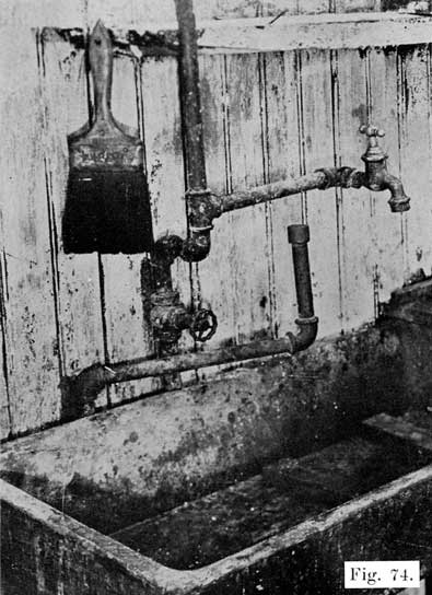
An ordinary sink may be used, as shown in Figure 74. This figure also shows a convenient arrangement for washing out jars. This consists of a three-fourths inch pipe having a perforated cap screwed over its upper end. Near the-floor is a valve which is normally held closed by a spring, and which has attached to it a foot operated lever. In washing sediment out of jars, the case is inverted over the pipe, and the water turned on by means of the foot lever. A number of fine, sharp jets of water are thrown up into the jar, thereby washing out the sediment thoroughly. |
Fig. 74. Sink with Faucet, and Extra Swinging Arm Pipe for Washing Out Jars. Four Inch Paint Brush for Washing Battery Cases |
Figures 76 and 77 give the working drawings for more elaborate wash tanks. The -water supply shown in Figure 74 may be used here, and the drain pipe arrangement shown in Figure 75 may be used if desired.
In joining the connectors and terminals to the positive and negative posts, and in joining plate straps to form a "group," the parts are joined or welded together, melting the surfaces to be joined, and then melting in lead from sticks called "burning lead." The process of joining these parts in this manner is known as "lead burning." Directions for "lead burning" are given on page 210.There are various devices by means of which the lead is melted during the "lead burning" process. The most satisfactory of these use a hot, pointed flame. Where such a flame is not obtainable, a hot carbon rod is used.
The methods are given in the following list in the order of their efficiency:
1. Oxygen and Acetylene Under Pressure in Separate Tanks. The gases are sent through a mixing valve to the burning tip. These gases give the hottest flame.
2. Oxygen and Hydrogen Under Pressure in Separate Tanks, Fig. 78. The flame is a very hot one and is very nearly as satisfactory as the oxygen and acetylene.
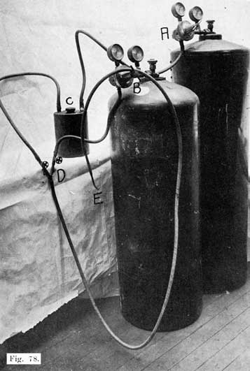
Fig. 78. Hydrogen-Oxygen Lead Burning Outfit. A and B are Regulating Valves. C is the Safety Flash Back Tank. D is the Mixing Valve. E is the Burning Tip. |
3. Oxygen and Illuminating Gas. This is a very satisfactory method, and one that has become very popular. In this method it is absolutely necessary to have a flash back tank (Fig. 79) in the gas line to prevent the oxygen from backing up into the gas line and making a highly explosive mixture which will cause a violent explosion that may wreck the entire shop.
Into one of these holes screw a short length of 1/4 inch pipe so Fig. 79. Flash-Back Tank for Lead Burning Outfit that it comes flush with the inner face of the cap. This pipe should lead to the burning outfit.
Into the other small hole screw a length of 1/4 inch pipe so that its lower end comes within 1/2 inch of the bottom of the trap. This pipe is to be connected to the illuminating gas supply.
To use the trap, fill within one inch of top with water, and screw a 1/2 inch plug into the center hole. All connections should be airtight.
4. Acetylene and Compressed Air. The acetylene is bought in tanks, and the air compressed by a pump.
5. Hydrogen and Compressed Air. This is the method that was very popular several years ago, but is not used to any extent at present because of the development of the first three methods. A special torch and low pressure air supply give a very satisfactory flame.
6. Wood Alcohol Torch. A hand torch with a double jet burner gives a very clean, nonoxidizing flame. The flame is not as sharp as the oxygen flame, and the torch is not easily handled without the use of burning collars and moulds. The torch has the advantage of being small, light and portable. A joint may be burned without removing the battery from the car.
7. Gasoline Torch. A double jet gasoline torch may be used, provided collars or moulds are used to prevent the lead from running off. The torch gives a broad flame which heats the parts very slowly, and the work cannot be controlled as easily as in the preceding methods.
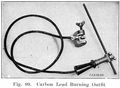
8. Carbon Arc. This is a very simple method, and requires only a spare 6 volt battery, a 1/4 inch carbon rod, carbon holder, cable, and clamp for attaching to battery. This outfit is shown in Fig. 80. It may be bought from the American Bureau of Engineering, Inc., Chicago, Ill. This outfit is intended to be used only when gas is not available, and not where considerable burning is to be done.In using this outfit, one terminal of an extra 6 volt battery is connected by a piece of cable -with the connectors to be burned. The contact between cable and connector should be clean and tight. The cable which is attached to the carbon rod is then connected to the other terminal of the extra battery, if the battery is not fully charged, or to the connector on the next cell if the battery is fully charged. The number of cells used should be such that the carbon is heated to at least a bright cherry red color when it is touching the joint which is to be burned together.
Sharpen the carbon to a pencil point, and adjust its position so that it projects from the holder about one inch. Occasionally plunge the holder and hot carbon in a pail of water to prevent carbon from overheating. After a short time, a scale will form on the surface of the carbon, and this should be scraped off with a knife or file.
In burning in a connector, first melt the lead of the post and connector before adding the burning lead. Keep the carbon point moving over all parts to be joined, in order to insure a perfectly welded joint.
9. Illuminating Gas and Compressed Air. This is the slowest method of any. Pump equipment is required, and this method should not be used unless none of the other methods is available.
The selection of the burning apparatus will depend upon individual conditions as well as prices, and the apparatus selected should be one as near the beginning of the foregoing list as possible. Directions for the manipulation of the apparatus are given by the manufacturers.
The most convenient arrangement for the lead burning outfit is to run pipes from one end of the work bench to the other, just below the center shelf. Then set the gas tanks at one end of the bench and connect them to the pipes. At convenient intervals have outlets for attaching the hoses leading to the torch.
EQUIPMENT FOR HANDLING SEALING COMPOUND
(a) Stove. Where city gas is available, a two or three burner gas stove or hot-plate should be used. Where there is no gas supply, the most satisfactory is perhaps an oil stove. It is now possible to get an odorless oil stove which gives a hot smokeless flame which is very satisfactory. In the winter, if a coal stove is used to heat the shop, the stove may also be used for heating the sealing compound, but it will be more difficult to keep the temperature low enough to prevent burning the compound.(b) Pot or Kettle. An iron kettle is suitable for use in heating compound. Special kettles, some of which are non-metallic, are on the market, and may be obtained from the jobbers.
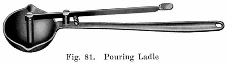
(c) An iron ladle should be obtained for dipping up compound, and for pouring compound when sealing a battery. Figure 81 shows a convenient form of ladle which has a pouring hole in the bottom. A taper pin, which is raised by the extra handle allows a very fine stream of compound to be poured.
The exact size of the ladle is not important, but one which is too heavy to be held in one hand should not be used.
(d) Several old coffee pots are convenient, and save much time in sealing batteries.
Sealing compound is a combination of heavy residues produced by the fractional distillation of petroleum. It is not all alike-that accepted for factory use and distribution to Service Stations must usually conform to rigid specifications laid down by the testing laboratories governing exact degrees of brittleness, elongation, strength and melting point. For these qualities it is dependent upon certain volatile oils which may be driven off from the compound if the temperature of the molten mass is raised above the comparatively low points where some of these oils begin to volatilize off as gaseous vapor or smoke.
Compound from which certain of these valuable constituent oils have been driven off or "burned out" through overheating is recognized through too great BRITTLENESS and SHRINKAGE on cooling, causing "CRACKED COMPOUND" with all of its attending difficulties.
Do not put too much cold compound in the kettle to begin with. It is not advisable to carry much more molten compound in the kettle at any time than can easily be dipped out-cold compound may be added during the day as needed. When there is considerable cold compound in the kettle and the,, heating flame is applied, the lower bottom part of the mass next to the surface of the iron is brought to a melting point first-heat must be conveyed from this already hot part of the compound upward throughout the whole mass-so that before the top part of it is brought to a molten condition the lower inside layers are very hot indeed. If there is too much in the kettle these lower layers are necessarily raised in temperature beyond the point where they lose some of their volatile oils-they are "burned" before the whole mass of compound can be brought to a molten state.Do not use too large a heating flame under the kettle. for the same reasons. A flame turned on "full blast" will certainly "burn" the bottom layers before the succeeding layers above are brought to the fusion point. USE A SLOW FLAME and TAKE TIME IN MELTING UP THE COMPOUND. It PAYS in the resulting jobs.
The more compound is heated, the thinner it becomes-it should never be allowed to become so hot that it flows too freely -it should never exceed the viscosity of medium molasses. It should flow freely enough to run in all narrow spaces but NOT freely enough to flow THROUGH them before it cools.
Stir the kettle frequently during the day. It is advisable about once a week to work as much compound out of the kettle as possible, empty that still remaining, clean the kettle out, and start with fresh compound.
NEVER USE OLD COMPOUND OVER AGAIN-that is, do not throw compound that has been dug out of used batteries into the kettle with the new compound. The old compound is no doubt acid soaked, and this acid will work through the whole molten mass, making a satisfactory job a very doubtful matter indeed.
Cold weather hardens sealing compound, of course, and renders it somewhat brittle and liable to crack. This tendency could be overcome by using a softer compound, but, on the other hand, compound so soft that it would have no tendency to crack in cold weather would be so soft in warm weather that it would fail to hold the assembly with the necessary firmness and security. It is far better policy to run the risk of developing a few cracks in the winter than a loose assembly in summer. Surface cracks developed in cold weather may be easily remedied by stripping off the compound around the crack with a heated tool, flashing with the torch and quickly re-sealing according to the above directions.
It is not practical to work any oil agent, such as paraffin or castor oil, into the compound in an effort to soften it for use in cold weather.
SHELVING AND RACKS
The essential things about shelving in a battery shop are, that it must be covered with acid-proof paint, and must be made of heavy lumber if it is to carry complete batteries. Figure 82 shows the heavy shelving required in a stock-room, while Figure 83 shows the lighter shelving which may be used for parts, such as jars, cases, extra plates, and so on.
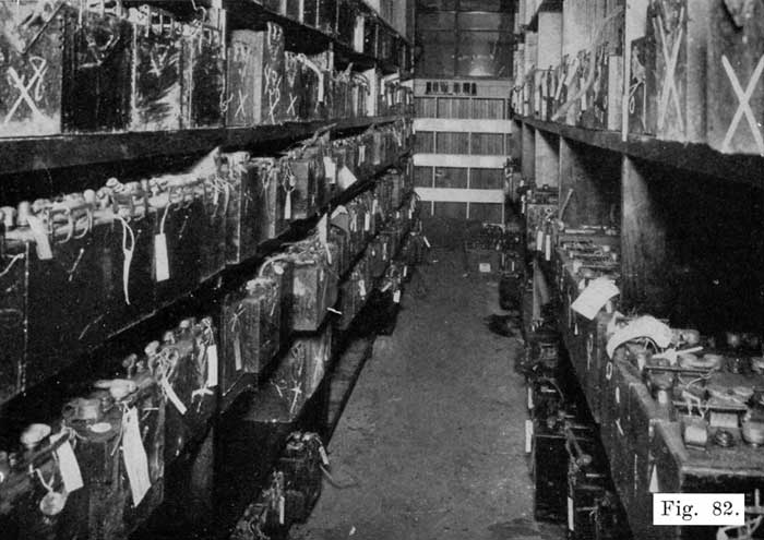
Fig 82. Typical Stockroom, Showing Heavy Shelving Necessary for Storing Batteries.
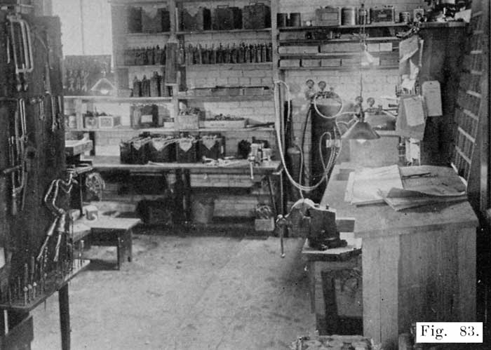
Fig. 83. Corner of Workshop, Showing Lead Burning Outfit, Workbench and Vises.
Figures 84 and 85 show two receiving racks for batteries which come in for repairs. In many shops batteries are set on the floor while waiting for repairs. If there is plenty of floor space, this practice is not objectionable. In any case, however, it improves the looks of the shop, and makes a better impression on the customer to have racks to receive such batteries. Note that the shelves are arranged so as to permit acid to drain off. Batteries often come in with wet, leaky cases, and this shelf construction is suitable for such batteries.
The racks shown in Figures 86 and 87 are for repaired batteries, new batteries, rental batteries, batteries in dry storage, and for any batteries which do not have wet leaky cases.
Figures 88 and 89 show racks suitable for new batteries which have been shipped filled with electrolyte, batteries in "wet" or "live" storage, rental batteries, and so on. Note that these racks are provided with charging circuits so that the batteries may be given a low charge without removing- them from the racks. Note. also that the shelves are spaced two feet apart so as to be able to take hydrometer readings, voltage readings, add water, and so on, without removing the batteries from the racks.
![]()
Figure 90 gives the dimensions for equipment bins suitable for covers, terminals, inter-cell connectors, jars, cases, and various other parts. These bins can be made with any desired number of sections, and additional sections built as they are needed.
Steaming is the most satisfactory method of softening sealing compound, making covers and jars limp and pliable. An open flame should never be used for this work, as the temperature of the flame is too high and there is danger of burning jars and covers and making them worthless. With steam, it is impossible to damage sealing compound or rubber parts.A soft flame from a lead burning torch is used to dry out the channels in the covers before sealing, and is run over the compound quickly to make the compound flow evenly and unite with the jars and covers. But in such work the flame is used for only a few seconds and is not applied long enough to do any damage.
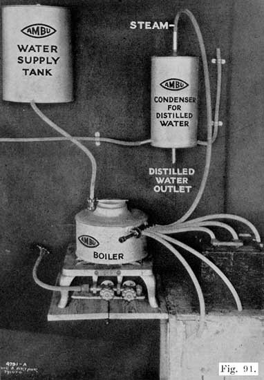
With a steaming outfit, it is also possible to distill water for use in mixing electrolyte and replacing evaporation in the cells. The only additional equipment needed is a condenser to condense the steam into water.
|
|
|
|
Fig. 91. Battery Steamer, with Steam Hose for Each Cell |
Figure 91 shows a steaming outfit mounted on a wall, and shows the rubber tube connections between the several parts. The boiler is set on the stove, water being supplied from the water supply tank which is hung above the boiler to obtain gravity feed. The water supply tank is open at the top, and is filled every morning with faucet water. This tank is suitable for any shop, even though a city water supply is available. A water pipe. from the city lines may be run to a point immediately above the tank and a faucet or valve attached. Where there is no city water supply, the tank may, of course, be filled with a pail or pitcher.The boiler is equipped with a float operated valve which maintains a one to one and one-half inch depth of water. As the water boils away, the float lowers slightly and allows water to enter the boiler. In this way, the water is maintained at the proper level at all times. A manifold is fitted to the boiler and has six openings to which lengths of rubber tubing are attached. These tubes are inserted in the vent holes of the battery which is to be steamed. Any number of the steam outlets may be opened by drawing out the manifold plunger valve to the proper point. When distilling water, a tube is attached to one of the steam outlets as shown, and connected to the condenser as shown. A bottle is placed under the distilled water outlet to collect the distilled water.
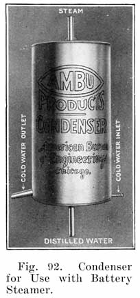
Cooling water enters the condenser through the tubing shown attached to the condenser at the lower right-hand edge. The other end of this tube is attached to the water faucet, or other cooling water supply. The cooling water outlet is shown at the lower left hand edge of the condenser. The cooling water inlet and outlet are shown in Figure 92.
If there is no city water supply, a ten or twenty gallon tank may be mounted above the condenser and attached by means of a rubber tube to the cooling water inlet shown at the lower right hand edge of the condenser in Figure 92. A similar tank is placed under the cooling water outlet. The upper tank is then filled with water. When the water has run out of the upper tank through the condenser and into the lower tank, it is poured back into the upper tank. In this way a steady supply of cooling water is obtained.
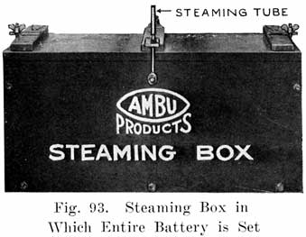
Another type of steamer uses a steaming box, Figure 93. The battery is placed in the box and steam is sent in through the cover. The boiler has only one steam outlet, and this is connected to the box by means of a hose.
If desired, a special bench may be made for the steaming outfit, as shown in Figure 94.The other tools needed for opening batteries, as given in the list on page 97 are standard articles, and may be obtained at any hardware store, except the terminal tongs, which should be purchased from a battery supply house.
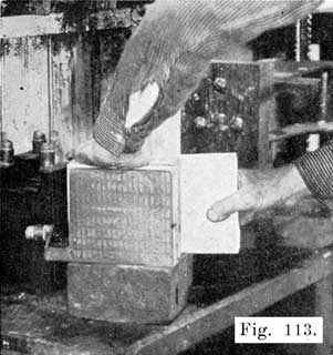
Figure 95 illustrates the use of terminal tongs. Battery terminals usually stick so tight that they must be forced out with pliers or other tools. Here is shown a pair of tongs that makes easy work of the job. One end has a fork and the other is shaped to come between the fork. It is placed on the battery terminal, as shown, and when the handles are brought together the terminal attached to the battery lead is forced out without marring any of the parts.
EQUIPMENT FOR LEAD BURNING (WELDING)
Plate Burning Rack
The plates which compose a "group" are joined to the plate connecting strap to which the post is attached. The plates are "burned" to the strap, and this must be done in such a manner that the plates are absolutely parallel, that the distance between plates is correct, and that the top surface of the strap is at right angles to the surface of the plates. These conditions are necessary in order that the positive and negative groups may mesh properly, that the complete element, consisting of the plates and separators may fit in the jar properly, and that the cell covers may fit over the posts easily.
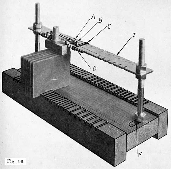
Fig. 96. Universal Plate Burning Rack. Will Hold Three Groups of Plates at One Time. Designed for Standard and Special Plates |
In order to secure these conditions, plates that are to be burned to the strap are set in a "burning rack," shown in Figs. 96 and 97, which consists mainly of a base upon which the plate rest, and a slotted bar into which the lugs on the plates fit. The distance between successive slots is equal to the correct distance between the plates of the group. An improved form of burning rack has a wooden base which has slots along the side. The plates are set into these slots and are thus held in the correct position at both top and bottom.
Fig. 97 shows a rack for use with 1/8 inch and 7-64 inch plates. Fig. 96 shows a "Universal" rack which may be used with both the 1/8 and 7-64 inch plates, and also many special plates.The guide-bar, or "comb," E, has slots along two sides, the base having corresponding slots, as shown. To accommodate different sized plates, the comb may be raised or lowered, and the uprights may be moved back and forth in two slots, one of which is shown at F. In using this rack, the plates are set in position, with their lower edges in the slots of the base, and their lugs in the slots in the comb. The plates are in this way held at opposite corners, and are absolutely straight and parallel.
Special fittings are provided to simplify the work of burning. A bar, D, fits along the edge of the comb, and holds the lugs of the plates firmly in the slots. This bar is movable to any part of the comb, being held by two spring clips, C. Two bars, A and B, which are adjustable, make a form around the plate lugs which will prevent the hot lead from running off while burning in the plates.
Instructions for burning on plates are given on page 217.
The triangular scraper, steel wire brush, coarse files and smoked or blue glasses are all standard articles and may be obtained from any supply house. The burning collars are made of iron, and are set over the end of inter-cell connectors when burning these to the posts, see Figure 98. Experienced repairmen generally do not use them, but those who have trouble with the whole end of the connector melting -and the lead running off should use collars to hold in the lead.
In every shop there is an accumulation of scrap lead from post drillings, old connecting straps, old plate straps, etc. These should be kept in a special box provided for that purpose, and when a sufficient amount has accumulated, the lead should be melted and run off into moulds for making burning- lead.The Burning Lead Mould is designed to be used for this purpose. As shown in Fig. 99, the mould consists of a sheet iron form which has been pressed into six troughs or grooves into which the melted lead is poured. This sheet iron form is conveniently mounted on a block of wood which has a handle at one end, making it possible to hold the mould while hot without danger of being burned. A sheet of asbestos separates the iron form from the wood, thus protecting the wood from the heat of the melted lead. A hole is drilled in the end of the handle to permit the mould being hung on a nail when not in use. The grooves in the iron form will produce bars of burning lead 15 inches long, 5-16 inch thick, 3/8 inch wide at the top, and 1/4 inch wide at the bottom.
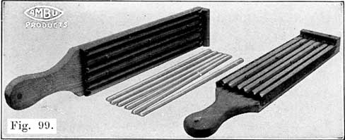
Fig. 99. Burning-Lead Moulds, and Burning Sticks Cast in Them
The advantage of this type of Burning Lead Mould over a cast iron mould is obvious. The form, being made of sheet iron, heats up very quickly, and absorbs only a very small amount of heat from the melted lead. The cast-iron mould, on the other hand, takes so much heat from the melted lead that the latter cools very quickly, and is hard to handle.An iron pot that will hold at least ten pounds of molten lead should be used in melting up lead scraps for burning sticks.
When the metal has become soft enough to stir with a clean pine stick skim off the dross. Continue heating metal until slightly yellow on top.
With a paddle or ladle drop in a cleaning compound of equal parts of powdered rosin, borax and flower of sulphur. Use a teaspoonful for a ten-pound melting and make sure the compound is perfectly dry.
Stir a little and if metal is at proper heat there will be a flare, flash or a little burning. A sort of tinfoil popcorn effect will be noticed floating on top of the metal. Stir until this melts down. Have your ladle hot and skim off soft particles. Dust the mould with mould compound, a powder which makes the lead fill the entire grooves, and not become cool before it does.
When everything is ready, fill the ladle and pour the lead into one of the grooves. Hold the ladle above one end of the groove while pouring, and do not move it along the groove. Fill the other grooves in a similar manner.
Post Builders. These are moulds which are set over the stumps of -posts which have been drilled short in removing the inter-cell connectors. Lead is then melted in with a burning flame to build the post up to the proper height. Figure 100 shows a set of post-builders, and Figure 101 illustrates their use.
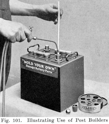
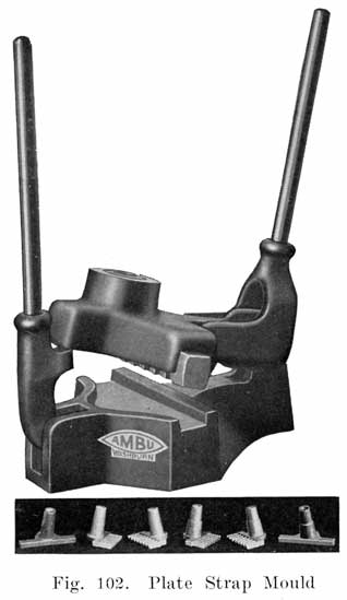
CONNECTORS AND TERMINALS
Moulds for Casting Inter-Cell Connectors, Terminals, Terminal
Screws, Taper Lugs, Plate Straps, Etc.
Figure 102 shows a plate strap mould with which three straps and posts may be cast in one minute. It has a sliding movable tooth rack for casting an odd or even number of teeth on the strap.
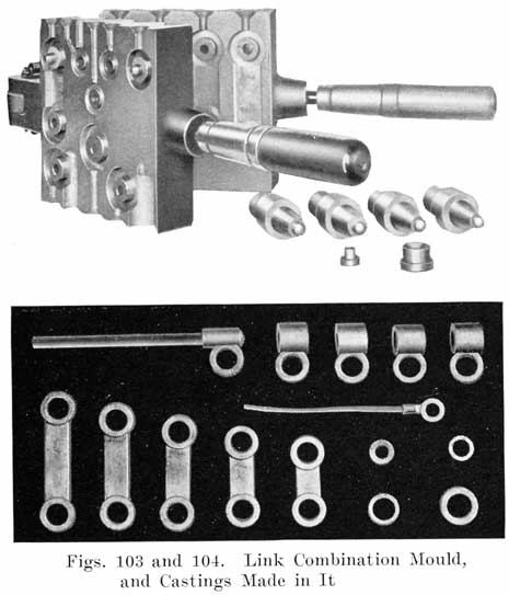
Figure 103 shows a Link Combination Mould which casts five inter-cell connectors for use on standard 7, 9, 11, 13 and 15 plate batteries, four end connectors (two Dodge tapers, and standard tapers, negative and positive), one end connector with 3/8 inch cable used on 12 volt Maxwell battery and on all other cars a wire cable, and- one small wire to connect with end post on batteries requiring direct connection. It also casts two post support rings to fit standard size rubber covers and to fit posts cast with plate strap mould, and two washers which are often needed when installing new or rental batteries.Figure 104 shows the parts which may be made with this mould.
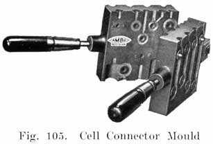
![]()
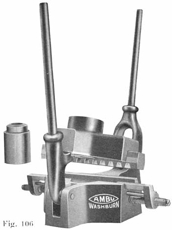
Figure 105 shows a cell connector mould which casts practically all the cell connectors used on standard 7, 9, 11, 13 and 15 plate batteries. This mould is similar to the Link Combination Mould shown in Figure 103.
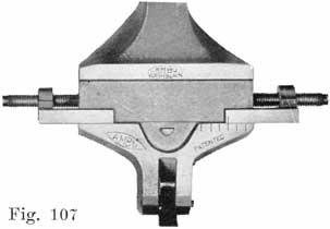
![]()
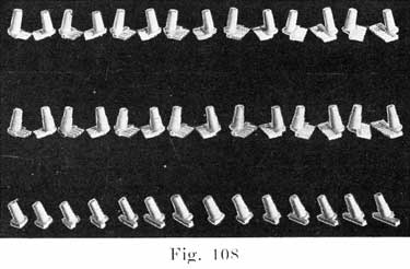
Figure 106 shows a production type strap mould which is designed to be used by large battery shops. Forty-two styles of straps are, cast by this mould. This mould has an indexing device as shown in Figure 107, which is adjusted by means of a screw for moulding the straps for any number of plates from seven to nineteen. Figure 109 shows some of tile castings which are made with this mould.
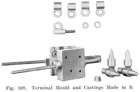
Figure 109 shows a Terminal Mould which casts five reversible end terminal connectors, a cable connector, such. as is used on the Maxwell battery, and two washers often needed in making a tight connection.
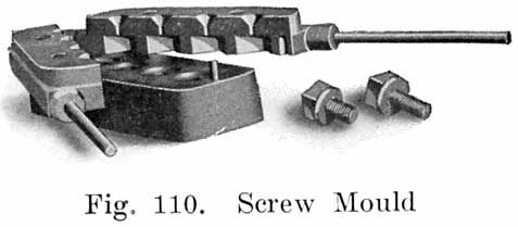
Figure 110 shows a Screw Mould which casts standard square lead leads on four screws in one operation, two 5/8 inch and two 3/8 inch. This mould has a screw adjustment in the base which makes each cavity adaptable to any length screw.
The acid proof asphaltum paint, paint brushes, wood chisels, wood plane, and earthenware jars are all standard articles.
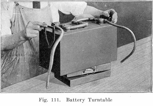
Figure 111 shows a battery turntable which is very convenient when painting cases, lead burning, etc.
TOOLS FOR GENERAL WORK
Most of the articles in this list require no explanation. Some of them, however, are of special construction.Separator Cutter. Some battery supply houses sell special separator cutters, but a large size photograph trimmer is entirely satisfactory.
|
|
|
Fig. 112. Plate Press for Pressing Swollen, Bulged Negatives (After Plates Have Been Fully Charged) |
Fig. 113. Inserting Plate Press Boards Between Negatives Preparatory to Pressing |
Plate Press. Figure 112 shows a special plate press in which the plates are pressed between wooden jaws. No iron can come into contact with the plates. This is a very important feature, since iron in solution causes a battery to lose its charge very quickly. This press is made of heavy hardwood timbers, and may be set on a bench or mounted on the -wall. A set of lead coated troughs carry away the acid which is squeezed from the plates.
This press- is designed for pressing negative plates, the active material of which has become bulged or swollen. A plate in this condition has a low capacity and cannot give good service. Swollen negatives often make it impossible to replace the plates in a jar. When negatives are found to be bulged or swollen, the battery must be fully charged, and the negatives then pressed. To do this, plate press boards, which are of acid proof material, and of the proper thickness are inserted between the negatives, as shown in Figure 113, and the plates are then set in the press is shown in Figure 114.
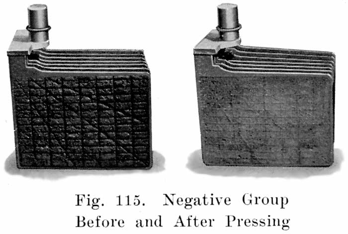
Figure 115 shows a group before and after pressing. Note that pressing has forced the active material back into the grid where it must be if the plates are to give good service. Never send out a battery with swollen or bulged negatives.Slightly buckled negatives may also be straightened out in the Plate Press. Positives do not swell or bulge as they discharge, but shed the active material. They are therefore not pressed Positives buckle, of course, but should never be pressed to straighten them. The lead peroxide of the positive plates is not elastic like the spongy the negatives, and if positives are pressed to straighten them the paste will crack and break from the grid. Slightly buckled positives may be used, but if they are so badly buckled that it is impossible to reassemble the element or put the element back into the jars, they should be discarded.
![]()
Battery Carrier. Figure 116 shows a very convenient battery carrier, having a wooden handle with two swinging steel hooks for attaching to the battery to be carried. With this type of carrier no strain is put on the handle, as is the case if a strap is -used.Battery Truck. When a battery must be moved any considerable distance, a truck, such as that shown in Figure 117 should be used. This truck may easily be made in the shop, or may be made at a reasonable cost in a carpenter shop. The rollers should be four inches or more in diameter and should preferably be of the ball-bearing type. Rubber tires on the rollers are a great advantage, since the rubber protects the rollers from acid and also eliminates the very disagreeable noise which iron wheels make, especially in going over a concrete floor or sidewalk. The repairman need not make his truck exactly like that shown in Figure 117, which is merely shown to give a general idea of how such a truck should be constructed.
The truck shown in Figure 117 was made from a heavy wooden box. With this construction lifting batteries is largely eliminated, which is most desirable, since a battery is not the lightest thing in the world. The battery is carried in a horizontal position and the truck is small enough to be wheeled between cars in the shop.
Another form of battery truck is shown in Figure 118, although this, is not as good as that shown in Figure 117.
CADMIUM TEST SET AND HOW TO MAKE THE TEST
As the cell voltage falls while the battery is on discharge, the voltage of the positive plates, and also the voltage of the negative plates falls. -When the battery is charged again the voltages of both positive and negative plates rise. If a battery gives its rated ampere-hour capacity on discharge, we do not care particularly how the voltages of the individual positive and negative groups change. If, however, the battery fails to give its rated capacity, the fault may be due to defective positives or defective negatives.If the voltage of a battery fails to come up when the battery is put on charge, the trouble may be due to either the positives or negatives. Positives and negatives may not charge at the same rate, and one group may become fully charged before the other group. This may be the case in a cell which has had a new positive group put in with the old negatives. Cadmium tests made while the battery is on charge will tell how fully the individual groups are charged.
Since the voltages of the positives and negatives both fall as a battery is discharged, and rise as the battery is charged, if we measure the voltages of the positives and negatives separately, we can tell how far each group is charged or discharged. If the voltage of each cell of a battery drops to 1.7 before the battery has given its rated capacity, we can tell which set of plates has become discharged by measuring the voltages of positives and negatives separately. If the voltage of the positives show that they are discharged, then the Positives are not up to capacity. Similarly, negatives are not up to capacity if their voltage indicates that they are discharged before the battery has given its rated capacity.
Cadmium readings alone do not give any indication of the capacity of a battery, and the repairman must be careful in drawing conclusions from Cadmium tests.
In general it is not always safe to depend upon Cadmium tests on a battery which has not been opened, unless the battery is almost new. Plates having very little active material, due to shedding, or due to the active material being loosened from the grid, will often give good Cadmium readings, and yet a battery with such plates will have very little capacity. Such a condition would be disclosed by an actual examination of the plates, or by a capacity discharge test.
To measure the voltages of the positives and negatives separately, Cadmium is used. The Cadmium is dipped in the electrolyte, and a voltage reading is taken between the Cadmium and the plates which are to be tested. Thus, if we wish to test the negatives, we take a voltage reading between the Cadmium and the negatives, as shown in Fig. 119. Similarly, if we wish to test the positives, we take a voltage reading between the Cadmium and the positives, as shown in Fig. 120.
![]()
![]()
In dipping the Cadmium into the electrolyte, we make two cells out of the battery cell. One of these consists of the Cadmium and the positives, while the other consists of the Cadmium and the negatives. If the battery is charged, the Cadmium forms the negative element in the Cadmium-Positives cell, and is the positive element in the Cadmium-Negatives cell. The voltage of the Cadmium does not change, and variations in the voltage readings obtained in making Cadmium tests are due to changes in the state of charge of the negative and positive plates which are being tested.What Cadmium Is: Cadmium is a metal, just like iron, copper, or lead. It is one of the chemical elements; that is, it is a separate and distinct substance. It is not made by mixing two or more substances, as for instance, solder is made by mixing tin and lead, but is obtained by separating the cadmium from the compounds in which it is found in nature, just as iron is obtained by treatment of iron ore in the steel mill.
When Cadmium Readings Should Be Made
1. When the battery voltage drops to 1.7 per cell on discharge before the battery has delivered its rated ampere-hour capacity, at the 5-hour rate when a discharge test is made.2. When a battery on charge will not "come up," that is, if its voltage will not come up to 2.5-2.7 per cell on charge, and its specific gravity will not come up to 1.280-1.300.
3. Whenever you charge a battery, at the end of the charge, when the voltage and specific gravity no longer rise, make Cadmium tests to be sure that both positives and negatives are fully charged.
4. When you put in a new group, charge the battery fully and make Cadmium tests to be sure that both the new and old groups are fully charged.
5. When a 20-minute high rate discharge test is made. See page 267.
That Cadmium Readings should be taken only while a battery is in action; that is, while it is on discharge, or while it is on charge.
Cadmium Readings taken on a battery which is on open circuit are not reliable.
When you are not using the Cadmium, it should be put in a vessel of water and kept there. Never let the Cadmium become dry, as it will then give unreliable readings.
Open Circuit Voltage Readings Worthless
Voltage readings of a battery taken while the battery is on open circuit; that is, when no current is passing through the battery, are not reliable. The voltage of a normal, fully charged cell on open circuit is slightly over 2 volts. If this cell is given a full normal discharge, so that the specific gravity of its electrolyte drops to 1.150, and is allowed to stand for several hours after the end of the discharge, the open circuit voltage will still be 2 volts. Open circuit voltage readings are therefore of little or no value, except when a cell is "dead," as a dead cell will give an open circuit voltage very much less than 2, and it may even give no voltage at all.
What the Cadmium Test Set Consists of
The Cadmium Tester consists of a voltmeter, Fig. 121, and two pointed brass prods which are fastened in wooden handles, as shown in Fig. 122. A length of flexible wire having a terminal at one end is soldered to each prod for attachment to the voltmeter. Fastened at right angles to one of the brass prods is a rod of pure cadmium.
Cadmium tests may be made with any accurate voltmeter which gives readings up to 2.5 volts in divisions of .05 volt.The instructions given below apply especially to the special AMBU voltmeter but these instructions may also be used in making cadmium tests with any voltmeter that will give the correct reading.
Fig. 121 is a view of the special AMBU Voltmeter, which is designed to be used specially in making Cadmium tests. Fig. 122 shows the Cadmium leads. The four red lines marked "Neg. Charged ... .. Neg. Discharged," "Pos. Charged,." and "Pos. Discharged," indicate the readings that should be obtained. Thus, in testing the positives of a battery on charge, the pointer will move to the line which is marked "Pos. Charged," if the positive plates are fully charged. In testing the negatives, the pointer will move to the line marked "Neg. Charged," which is to the left of the "0" line, if the negatives are fully charged, and so on. Figs. 123, 124, 125 and 126 show the pointer in the four positions on the scale which it takes when testing fully charged or discharged plates. In each figure the pointer is over one of the red lines on the scale. These figures also show the readings, in volts, obtained in making the cadmium tests on fully charged or completely discharged plates.
If Pointer Is Not Over the "0" Line: It sometimes happens, in shipping the instrument, and also in the use of it, that the pointer does not stand over the "0" line, but is a short distance away. Should you find this to be the case, take a small screwdriver and turn the screw which projects through the case, and which is marked "Correct Zero," so as to bring the pointer exactly over the "0" line on the scale while the meter has no wires connected to its binding posts.Connections of Cadmium Leads: In making Cadmium Tests, connect the prod which has the cadmium fastened to it to the negative voltmeter binding post. Connect the plain brass prod to the positive voltmeter binding post. The connections to the AMBU Cadmium Voltmeter are shown in Fig. 127.
Testing a Battery on Discharge
The battery should be discharging continuously, at a constant, fixed rate, see page 265.
Generally, on a starting ability test (see page 267), the positive Cadmium readings will start at about 2.05 volts for a hard or very new set of positives, and at 2.12 volts or even higher for a set of soft or somewhat developed positives, and will drop during the test, ending at 1.95 volts or less. The negative Cadmium readings will start at 0.23 volt or higher, up to 0.30, and will rise gradually, more suddenly toward the end if the plates are old, ending anywhere above 0.35 and up to 0.6 to 0.7 for poor negatives.Short Circuited Cells: In cases of short circuited cells, the voltage of the cell will be almost down to zero. The Cadmium readings would therefore be nearly zero also for both positives and negatives. Such a battery should be opened for inspection and repairs.
The Battery should be charging at the finishing rate. (This i's usually stamped on the battery box.) Dip the cadmium in the electrolyte as before, and test the negatives by holding the plain prod on the negative post of the cell. See Fig. 119. Test the positives in a similar manner. See Fig. 120. The cell voltage should also be measured. If the positives are fully charged, the positive cadmium reading will be such that the pointer will move to the red line marked "Pos. Charged." See Fig. 125. If you are using an ordinary voltmeter, the meter will give a reading of from 2.35 to 2.42 volts. The negatives are then tested in a similar manner. The negative-cadmium reading on an ordinary voltmeter will be from .175 to .2 to the left of the "0" line; that is, the reading is a reversed one. If you are using the special ABM voltmeter, the pointer will move to the red line marked "Neg. Charged." See Fig. 123. The cell voltage should be the sum of the positive-cadmium and the negative cadmium readings.If the voltage of each cell will not come up to 2.5 to 2.7 volts on charge, or if the specific gravity will not rise to 1.280 or over, make the cadmium tests to determine whether both sets of plates, or one of them, give readings indicating that they are fully charged. If the positives will not give a reading of at least 2.35 volts, or if the negatives will not give a reversed reading of at least 0.1 volt, these plates lack capacity.
In case of a battery on charge, if the negatives do not give a minus Cadmium reading, they may be lacking in capacity, but, on the other hand, a minus negative Cadmium reading does not prove that the negatives are up to hill capacity. A starting ability discharge test (page 267) is the only means of telling whether a battery is up to capacity.
Improperly treated separators will cause poor negative-Cadmium readings to be obtained. The charging rate should be high enough to give cell voltages of 2.5-2.7 when testing negatives. Otherwise it may not be possible to get satisfactory negative-Cadmium reading. Separators which have been allowed to become partly dry at any time will also make it difficult to obtain satisfactory negative-Cadmium readings.
(See page 265 for directions for making tests.)
Figure 128 shows a high rate discharge cell tester. It consists of a handle carrying two heavy prongs which are bridged by a length of heavy nichrome wire. When the ends of the prongs are pressed down on the terminals of a cell, a current of 150 to 200 amperes is drawn from the cell. A voltage reading of the cell, taken while this discharge current is flowing is a means of determining the condition of the cell, since the heavy discharge current duplicates the heavy current drawn by the starting motor. Each prong carries a binding post, a low reading voltmeter being connected to these posts while the test is made. This form of discharge tester is riot suitable for making starting ability discharge tests, which are described on page 267.Other forms of high rate discharge testers are made, but for the shop the type shown in Figure 128 is most convenient, since it is light and portable and has no moving parts, and because the test is made very quickly without making any connections to the battery. Furthermore, each cell is tested separately and thus six or twelve volt batteries may be tested without making any change in the tester.
For making starting ability discharge tests at high rates, a carbon plate or similar rheostat is most suitable, and such rheostats are on the market.
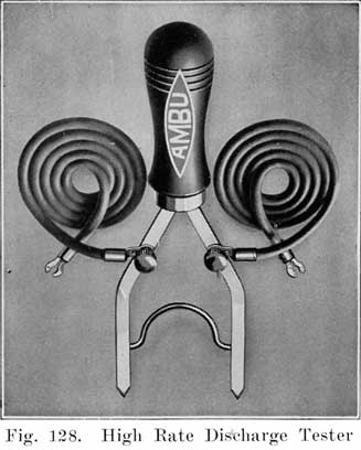
![]()
Paper tags are not acid proof, and if acid is spilled on tags tied to batteries which are being repaired, the writing on the tags is often obliterated so that it is practically impossible to identify the batteries. An excellent plan to overcome this trouble is to dip the tags in hot paraffine after they have been properly filled out. The writing on the tags can be read easily and since paraffine is acid proof, any acid which may be spilled on the paraffine coated tags will not damage the tags in any way.Figure 129 shows a paraffine dip pot. A small earthenware jar is best for this purpose. Melt the paraffine slowly on a stove, pour it into the pot, and partly immerse a 60-watt carbon lamp in the paraffine as shown. The lamp will give enough heat to keep the paraffine melted, without causing it to smoke to any extent. After filling out a Battery Card, dip it into the Paraffine, and hold the card above the pot to let the excess paraffine run off. Let the paraffine dry before attaching the tag to the battery, otherwise the paraffine may be scratched off.
WOODEN BOXES FOR BATTERY PARTS
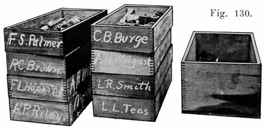
Fig. 130. Boxes for Holding Parts of Batteries Being Prepaired
Figure 130 shows a number of wooden boxes, about 12 inches long, 8 inches wide, and 4 inches deep. These boxes are very useful for holding the terminals inter-cell connectors, covers, plugs, etc., of batteries which are dismantled for repairs. Write the name of the owner with chalk on the end of the box, and rub the name off after the battery has been put together again. The boxes shown in Figure 130 had been used for plug tobacco, and served the purpose very well. The larger box shown in Figure 130 may be used for collecting old terminals, inter-cell connectors, lead drillings, etc.
The twenty gallon size is very convenient for waste acid, old separators, and any junk parts which are wet with acid. The jars are acid proof and will help keep the shop floor dry and anything which will help in this is most desirable.
Acid is shipped in large glass bottles around each of which a wooden box is built to prevent breakage, the combination being called a "carboy." Since the acid is heavy, some means of drawing it out of the bottle is necessary. One method is illustrated in Figure 131, wooden rockers being screwed to the box in which the bottle is placed.
A very good addition to the rockers shown in Figure 131 is the inner tube shown in Figure 132. In this illustration the rockers are not shown, but should be used. The combination of the rockers with the inner tube gives a very convenient method of pouring acid from a carboy, since the heavy bottle need not be lifted, and since it helps keep the floor and the top of the box dry.
The rubber tube shown in Figure 132 is a piece of 4 inch inner tube which is slit down one side to make it lie flat. Near one end is cut a hole large enough to fit tightly over the neck of the acid bottle. Slip this rubber over the neck of the bottle and allow the long end to hang a few inches over the side of the carboy bottle or box. This is for pouring acid from a carboy when it is too full to allow the contents to be removed without spilling. This device will allow the contents of the carboy to be poured into a crock or other receptacle placed on the floor without spilling, and also prevents dirt that may be laying on top of the carboy from falling into the crock.
Figure 133 shows a siphon method for drawing acid from a bottle, although this method is more suitable for distilled water than for acid. "A" is the bottle, "B" a rubber stopper, "C" and "D" are 3/8 inch glass or hard rubber tubes, "E" is a length of rubber tubing having a pinch clamp at its lower end. To use this device, the stopper and tubes are inserted in the bottle, and air blown or pumped in at "C," while the pinch clamp is open, until acid or water begins to run out of the lower end of tubing ""E." The pinch clamp is then released. Whenever acid or water is to be drawn from the bottle the pinch clamp is squeezed so as to release the pressure on the tube. The water or acid will flow down the tube automatically as long as the pinch clamp is held open. The clamp may be made of flat or round spring brass or bronze. This is bent round at (a). At (c) an opening is made, through which the part (b) is bent. The clamp is operated by pressing at (d) and (e). The rubber tubing is passed through the opening between (b) and (c). |
|
Figure 134 shows another arrangement, using a tire pump. D and E are 3/8 inch hard rubber tubes. D is open at both ends and has a "T" branch to which the pump tubing is attached. To operate, a finger is held over the upper end of D, and air is pumped into the acid bottle, forcing the acid into the vessel F. To stop the flow of acid, the finger is removed from D. This stops the flow instantly. This method is the most satisfactory one when fairly large quantities of acid or water are to be drawn off.
The degree of success which the battery repairman attains depends to a considerable extent upon the workshop in which the batteries are handled. It is, of course, desirable to be able to build your shop, and thus be able to have everything arranged as you wish. If you must work in a rented shop, select a place which has plenty of light and ventilation. The ventilation is especially important on account of the acid fumes from the batteries. A shop which receives most of its light from the north is the best, as the light is then more uniform during the day, and the direct rays of the sun are avoided. Fig. 38 shows a light, well ventilated workroom.The floor should be in good condition, since acid rots the wood and if the floor is already in a poor condition, the acid will soon eat through it. A tile floor, as described below, is best. A wooden floor should be thoroughly scrubbed, using water to which baking soda has been added. Then give the floor a coat of asphaltum paint, -which should be applied hot so as to flow into all cracks in the wood. When the first coat is dry, several more coats should be given. Whenever you make a solution of soda for any purpose, do not throw it away when you are through with it. Instead, pour it on the floor where the acid is most likely to be spilled. This will neutralize the acid and prevent it from rotting the wood.
If you can afford to build a shop, make it of brick, with a floor of vitrified brick, or of tile which is not less than two inches thick, and is preferably eight inches square. The seams should not be less than one-eighth inch wide, and not wider than one fourth. They should be grouted with asphaltum, melted as hot and as thin as possible (not less than 350° F.). This should be poured in the seams. The brick or tile should be heated near the seams before pouring in the asphaltum. When all the seams have been filled, heat them again. After the second heating, the asphaltum may shrink, and it may be necessary to pour in more asphaltum.
If possible, the floor should slope evenly from one end of the room to the other. A lead drainage trough and pipe at the lower end of the shop will carry off the acid and electrolyte.
It is a good plan to give all work benches and storage racks and shelves. at least two coatings of asphaltum paint. This will prevent rotting by the acid.
The floor of a battery repair shop is, at best, a wet, sloppy affair, and if a lead drainage trough is too expensive, there should be a drain in the center of the floor if the shop is small, and several if the shop is a large one. The floor should slope toward the drains, and the drain-pipes should be made of glazed tile.
To keep the feet as dry as possible, rubbers, or even low rubber boots should be worn. Sulphuric acid ruins leather shoes, although leather shoes can be protected to a certain extent by dipping them in hot paraffine.
A good plan is to lay a wooden grating over the floor as shown in Figure 135. Water and acid will run down between the wooden strips, leaving the walking surface fairly dry. If such a grating is made, it should be built in sections which may be lifted easily to be washed, and to permit washing the floor. Keep both the grating and the floor beneath covered with asphaltum paint to prevent rotting by acid. Once a week, or oftener, if necessary, sweep up all loose dirt and then turn the hose on the floor and grating to wash off as much acid as possible. When the wood has dried, a good thing to do is to pour on the floor and grating several pails of water in which washing soda or ammonia has been dissolved.Watch your floor. It will pay-in better work by yourself and by the men working for you. Have large earthenware jars set wherever necessary in which lead drillings, old plates, old connectors, old separators, etc., may be thrown. Do not let junk cases, jars, separators, etc., accumulate. Throw them away immediately and keep your shop clean. A clean shop pleases Your customers, --and satisfied customers mean success.
On the following pages a number of shop layouts are given for both large and small shops. The beginner, of course, may not be able to rent even a small shop, but he may rent part of an established repair shop, and later rent an entire shop. A man working in a corner of an established service must arrange his equipment according to the space available. Later on, when he branches out for himself, he should plan his shop to got the best working arrangement. Figure 136 shows a suggested layout for a small shop. Such a layout may have to be altered because of the size and shape of the shop, and the location of the windows.
As soon as growth of business permits, a shop should have a drive-in, so that the customer may bring his car off the street. Without a drive-in all testing to determine what work is -necessary will have to be done at the curb, which is too public for many car owners. A drive-in is also convenient if a customer leaves his car while his battery is being repaired. To a certain extent, the advantages of a drive-in may be secured by having a vacant lot next to the shop, with a covering of cinders. As soon as possible, however, a shop which is large enough to have a drive-in should be rented or built.Figure 137 shows a 24 x 60 shop with space for three cars. The shop equipment is explained in the table.
Figure 138 shows a 40 x 75 shop with room for six cars and a drive-in and drive-out. This facilitates the handling of the cars.
Figure 139 shows a 30 x 100 shop in a long and somewhat narrow building. It also has a drive-in and drive-out.
Another arrangement for the same sized shop as shown in the preceding illustration is shown in Figure 140. Here the drive-out is at the side and this layout is, therefore, suitable for a building located on a corner, or next to an alley.
Figure 141 shows a larger shop, which may be used after the business has grown considerably.
Figure 142 shows a layout suitable for the largest station.
Somewhere between Figures 136 and 142 is a layout for any service station. The thing to do is to select the one most suitable for the size of the business, and to fit local conditions, If a special building is put up, local conditions are not so important,
If a shop is rented, it may not be possible to follow any of the layouts shown in Figs. 136 to 142. However, the layout which is best adapted for the actual shop should be selected as a guide, and the equipment shown obtained. This should then be arranged as nearly like the pattern layout as the shop arrangement will permit.
Light is essential to good work, so you must have plenty of good light and at the right place. For a light that is needed from one end of a bench to the other, to look into each individual battery, or to take the reading of each individual battery, there is nothing better than a 60 Watt tungsten lamp under a good metal shade, dark on outside and white on inside.A unique way to hang a light and have it movable from one end of the bench to the other, is to stretch a wire from one end of the bench to the other. Steel or copper about 10 or 12 B & S gauge may be used. Stretch it about four or five feet above top of bench directly above where the light is most needed. If You have a double charging bench, stretch the wire directly above middle of bench. Before fastening wire to support, slip an old fashioned porcelain knob (or an ordinary thread spool) on the wire. The drop cord is to be tied to this knob or spool at whatever height you wish the light to hang (a few inches lower than your head is the right height).
Put the ceiling rosette above center of bench; cut your drop cord long enough so that you can slide the light from one end of bench to the other after being attached to rosette. Put vaseline on the wire so the fumes of gas will not corrode it. This will also make the spool slide easily. This gives you a movable, flexible light, with which you will reach any battery on bench for inspection. The work bench light can be rigged up the same way and a 75 or 100 Watt nitrogen lamp used.
![]()
Fig. 137 and 138: A- Receiving Rack. B-Portable Electric Drill, or Hand Drill. C-Wash Tank, D-Tear Down Bench. E-Hot Water Pan. F-Waiting Rack (5 Shelves). G-Repair Bench (6 ft. by 2 ft. 3 in.). H-Charging Table (3 Circuits). I-Electrolyte(10 Gal. Crocks). J-Separator Rack. K-Generator. L-Switchboard. M-Stock Bins, N-New Batteries, O-Live storage. P-Sealing Compound. R-Ready Rack (5-Shelves). S-Dry Storage. (S is not in Fig. 137.)
![]()
![]()
Fig. 139, 140 and 141: A- Receiving Rack. B-Power Drill. C-Wash Tank. D-Tear Down Bench. E-Hot Water Pan. F-Waiting Rack (6 Shelves). G-Repair Bench. H-Charging Table (3 Circuits). I-Electrolyte (10 Gal. Crocks). J-Separator Rack. K-Generator. L-Switchboard. M-Stock Bins. N-New Batteries. O-Live storage. P-Sealing Compound. R-Ready Rack (5-Shelves). S-Dry Storage. T-Torn Down Parts. (O and T in 141, not in 139 and 140.)
Fig. 142: A- Receiving Rack. B-Power Drill. C-Wash Tank. D-Tear Down Bench. E-Hot Water Pan. F-Waiting Rack (6 Shelves). G-Repair Bench. H-Charging Table. I-Electrolyte (10 Gal. Crocks). J-Separator Rack. K-Generator. L-Switchboard. M-Stock Bins. N-New Batteries. O-Live storage. P-Sealing Compound. R-Ready Rack. S-Dry Storage. T-Torn Down Parts.
|
|
|
| |||||||||