CHAPTER 12
GENERAL SHOP INSTRUCTIONS
CHARGING BATTERIES
The equipment for charging batteries, instructions for building and wiring charging benches have already been given. What we shall now discuss is the actual charging. The charge a battery receives on the charging bench is called a "bench charge."
Battery charging in the service station may be divided into two general classes:
1. Charging batteries which have run down, but which are otherwise in good condition, and which do not require repairs.2. Charging batteries during or after the repair process.
The second class of charging is really a part of the repair process and will-be described in the chapter on "Rebuilding the Battery." Charging a battery always consists of sending a direct current through it, the current entering the battery at the positive terminal and leaving it at the negative terminal, the charging current, of course, passing through the battery in the opposite direction to the current which the battery produces when discharging. When a battery discharges chemical changes take place by means of which electrical energy is produced. When a battery is on charge, the charging current causes chemical changes which are the reverse of those which take place on discharge and which put the active materials and electrolyte in such a condition that the battery serves as a source of electricity when replaced in the car.
Batteries are charged not only in a repair shop but also in garages which board automobiles, and in car dealers' shops. No matter where a battery is charged, however, the same steps must be taken and the same precautions observed.
When a Bench Charge is Necessary:
(a) When a battery runs down on account of the generator on the car not having a sufficient output, or on account of considerable night driving being done, or on account of frequent use of the starting motor, or on account of neglect on the part of the car owner.
(b) Batteries used on cars or trucks without a generator, or batteries used for Radio work should, of course, be given a bench charge at regular intervals.
(c) When the specific gravity readings of all cells are below 1.200, and these readings are within 50 points of each other.
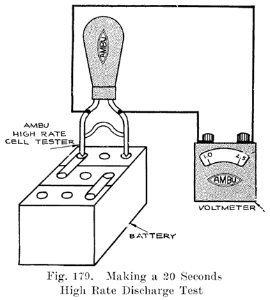
Should the gravity reading of any cell be 50 points lower or higher than that of the other cells, it is best to make a 15-seconds high rate discharge test (see page 266) to determine whether the cell is defective or whether electrolyte has been lost due to flooding caused by over-filling and has been replaced by water or higher gravity electrolyte. If any defect shows up during the high rate test, the battery should be opened for inspection. If no defect shows up, put the battery on charge.
(d) When the lamps burn dimly while the engine is running.
(e) When the lamps become very dim when the starting switch is closed.
If a battery is tested by turning on the lights and then closing the starting switch, make sure that there is no short-circuit or ground in the starting motor circuits. Such trouble will cause a very heavy current to be drawn from the battery, resulting in a drop in the voltage of the battery.
(f) When the voltage of the battery has fallen below 1.7 volts per cell, measured while all the lights are turned on.
(g) When the owner has neglected to add water to the cells regularly, and the electrolyte has fallen below the tops of the plates.
(h) When a battery has been doped by the addition of electrolyte or acid instead of water, or when one of the "dope" electrolytes which are advertised to make old, worn out batteries charge up in a ridiculously short time and show as much life and power as a new battery. Use nothing but a mixture of distilled water and sulphuric acid for electrolyte. The "dope" solutions are not only worthless, but they damage a battery considerably and shorten its life. Such a "doped" battery may give high gravity *readings and yet the lamps will become very dim when the starting motor cranks the car, the voltage per cell will be low when the lights are burning, or low voltage readings (1.50 per cell) will be obtained if a high rate discharge test is made.
Every battery which comes in for any reason whatsoever, or any battery which is given a bench charge whenever necessary should also be examined for other defects, such as poorly burned on connectors and terminals, rotted case, handles pulled off, sealing compound cracked, or a poor sealing job between the covers and jars, or covers and posts. A slight leakage of electrolyte through cracks or imperfect joints between the covers and jars or covers and posts is very often present without causing any considerable trouble. If any of the other troubles are found, however, the battery needs repairing.
Arrangement of Batteries on Charging Bench. If a battery comes in covered with dirt, set it on the wash rack or in the sink and clean it thoroughly before putting it on charge. In setting the batteries on the charging bench, place all of them so that the positive terminal is toward the right as you face the bench. The positive terminal may be found to be painted red, or may be stamped "+", "P", or "POS". If the markings on one of the terminals has been scratched or worn off, examine the other terminal. The negative terminal may be found to be painted black, or be stamped "-", "N" or "NEG".
If neither terminal is marked, the polarity may be determined with a voltmeter, or by a cadmium test. To make the voltmeter test, hold the meter wires on the battery terminals, or the terminals of either end cell. When the voltmeter pointer moves to the right of the "0" line on the scale, the wire attached to the "+" terminal of the meter is touching the positive battery terminal, and the wire attached to the "-" terminal of the meter is touching the negative battery terminal. If this test is made with a meter having the "0" line at the center of the scale, be sure that you know whether the pointer should move to the left or right of the "0" line when the wire attached to the "+" meter terminal is touching the positive battery terminal.
Another method of determining which is the positive terminal of the battery is to use the cadmium test. When a reading of about two volts is obtained, the prod held on one of the cell terminals is touching the positive terminal. When a reading of almost zero is obtained, that is, when the needle of the meter just barely moves from the "0" line, or when it does not move at all, the prod held on one of the cell terminals is touching the negative terminal. This test, made while the battery is on open-circuit, is not a regular cadmium test, but is made merely to determine the polarity of the battery.
The polarity of the charging line will always be known if the bench is wired permanently. The positive charging wire should always be to the right. If a separate switch is used for each battery (Figures 43 and 65), the wire attached to the right side of the switch is positive. If the batteries are connected together by means of jumpers (Figures 44 and 47), the positive charging wire should be at the right hand end of the bench as seen when facing the bench. If a constant-potential charging circuit is used as shown in Figure 48, the positive bus-bar should be at the top and the neutral in the center, and the negative at the bottom.
If the polarity of the charging line wires is not known, it may be determined by a voltmeter, in the same way as the batter-, polarity is determined. If this is done, care should be taken to use a meter having a range sufficient to measure the line voltage. If no such voltmeter is available, a simple test is to fill a tumbler with weak electrolyte or salt water and insert two wires attached to the line. The ends of these wires should, of course, be bare for an inch or more. Hold these wires about an inch apart, with the line alive. Numerous fine bubbles of gas will collect around the negative wire.
With the polarities of all the batteries known, arrange them so that all the positive terminals are at the right. Then connect them to the individual switches (see Figure 43), or connect them together with jumpers (see Figure 44), being sure to connect the negative of one battery to the positive of the next. Connect the positive charging line wire to the positive terminal of the first battery, and the negative line wire to the negative terminal of the last battery. See page 105.
With all connections made, and before starting to charge, go over all the batteries again very carefully. You cannot be too careful in checking the connections, for if one or more batteries are connected reversed, they will be charged in the wrong direction, and will most likely be severely damaged.
As a final check on the connections of the batteries on the line, measure the total voltage of these batteries and see if the reading is equal to two times the total number of cells on the line.
Now inspect the electrolyte in each cell. If it is low, add distilled water to bring the electrolyte one-half inch above the plates. Do not wait until a battery is charged before adding water. Do it now. Do not add so much water that the electrolyte comes above the lower end of the vent tube. This will cause flooding.
Charging, Rate. If you connect batteries of various sizes together on one circuit, charge at the rate which is normal for the smallest battery. If the rate used is the normal one for the larger batteries, the smaller batteries will be overheated and "boiled" to death, or they may gas so violently as to blow a considerable portion of the active material from the plates.
It is quite possible to charge 6 and 12 volt batteries in series. The important point is not to have the total number of cells too high. For instance, if the 10 battery Tungar is used, ten 6-volt batteries (30 cells), or any combination which gives 30 cells or less may be used. For instance, five 12-volt batteries (30 cells), or six 6-volt batteries (18 cells) and two 12-volt batteries (12 cells), or any other combination totaling 30 cells may be used. The same holds true for motor-generators.
The charging rate is generally determined by the size of the charging outfit. The ten battery Tungar should never have its output raised above 6 amperes. A charging rate of 6 amperes is suitable for all but the very smallest batteries. In any case, whether you are certain just what charging rate to use, or not, there are two things which will guide you, temperature and gassing.
1. Temperature. Have a battery thermometer (Figure 37) on hand, and measure the temperature of the electrolyte of each cell on the line. If you note that some particular cell is running hotter than the others, keep the thermometer in that cell and watch the temperature. Do not let the temperature rise above 110 degrees Fahrenheit, except for a very short time. Should the highest of the temperature of the cells rise above 110 degrees, reduce the charging rate.
2. Gassing. Near the end of a charge and when the specific gravity has stopped rising, or is rising very slowly, bubbles of gas will rise from the electrolyte, this being due to the charging current decomposing the water of the electrolyte into hydrogen and oxygen. If this gassing is too violent, a considerable amount of active material will be blown from the plates. Therefore, when this gassing begins, the charging rate should be reduced, unless the entire charging has been done at a low rate, say about five amperes.
If gassing begins in any cell soon after the charge is started, or before the specific gravity has reached its highest point, reduce the charging rate to eliminate the gassing.
If one battery or one cell shows a high temperature and the others do not, or begins gassing long before the others do, remove that battery from the charging line for further investigation and replace it with another so as not to slow up the charge of the other batteries which are acting normally.
As long as excessive temperatures and too-early gassing are avoided, practically any charging rate may be used, especially at the start. With a constant potential charging set, as shown in Figure 48, the charge may start at as high a rate as 50 amperes. If this system of charging is used, the temperature must be watched very carefully and gassing must be looked for. With the usual series method of charging, a charge may, in an emergency, be started at 20 amperes or more. As a general rule do not use a higher rate than 10 amperes. A five ampere rate is even better, but more time will be required for the charge.
Time Required for a Charge. The time required is not determined by the clock, but by the battery. Continue the charge until each cell is gassing freely (not violently) and for five hours after the specific gravity has stopped rising. The average condition of batteries brought in for charge permits them to be fully charged in about 48 hours, the time being determined as stated above. Some batteries may charge fully in less time, and some may require from four days to a week, depending entirely upon the condition of the batteries. Do not give any promise as to when a recharge battery will be ready. No one can tell how long it will take to charge.
Specific Gravity at the End of the Charge. The specific gravity of the electrolyte in a fully charged cell should be from 1.280 to 1.300. If it varies more than 10 points above or below these values, adjust it by drawing off some of the electrolyte with a hydrometer and adding water to lower the gravity, or 1.400 acid to raise the gravity. After adjusting the gravity charge for one hour more.
Battery Voltage at End of Charge. The voltage of a fully charged cell is from 2.5 to 2.7 when the temperature of the electrolyte is 80 degrees Fahrenheit; 2.4 to 2.6 when the temperature of the electrolyte is 100 degrees Fahrenheit, and 2.35 to 2.55 volts when the temperature of the electrolyte is 120 degrees Fahrenheit, and this. voltage, together with hydrometer readings of 1.280-1.300 indicate that the battery is fully charged.
Just before putting a battery which has been charged into service, give it a 15 seconds high rate discharge test, see page 266.
Painting. Before returning a battery to the owner wipe it perfectly clean and dry. Then wipe the covers, terminals, connectors and handles with a rag wet with ammonia. Next give the case a light coat of black paint which may be made by mixing lamp black and shellac. This paint dries in about five minutes and gives a good gloss. The customer may not believe that you are returning the battery which he brought in but he will most certainly be pleased with your service and will feel that if you take such pains with the outside of his battery you will certainly treat the inside with the same care when repairs are necessary. The light coat of paint costs very little for one battery, but may bring you many dollars worth of work.
Level of Electrolyte. During charge the electrolyte will expand, and will generally flow out on the covers. This need not be wiped off until the end of the charge. When the electrolyte has cooled after the battery is taken off charge, it must be about 1/2 inch above the plates. While the electrolyte is still warm it will stand higher than this, but it should not be lowered by drawing off some of it, as this will probably cause it to be below the tops of the plates and separators when it cools.
If all goes well, the charging process -will take place as described in the preceding paragraphs. It frequently happens, however, that all does not go well, and troubles arise. Such troubles generally consist of the following:Specific gravity will not rise to 1.280. This may be due to the plates not taking a full charge, or to water having been used to replace electrolyte which has been spilled. To determine which of these conditions exist, make cadmium test (see page 174) on the positives and negatives, also measure the voltage of each cell. If these tests indicate that the plates are fully charged (cell voltage 2.5 to 2.7, Positive-Cadmium 2.4 volts, Negative-Cadmium minus 0.15 to 0.20 volts), you will know that there is not enough acid in the electrolyte. The thing to do then is to dump out the old electrolyte, refill with 1.300 electrolyte and continue the charge until the specific gravity becomes constant. Some adjustment may then have to be made by drawing off some of the electrolyte with a hydrometer and adding water to lower the gravity, or 1.400 acid to bring it up. Remember that specific gravity readings tell you nothing about the plates, unless it is known that the electrolyte contains the correct proportions of water and acid. The cadmium test is the test which tells you directly whether or not the plates are charged and in charging a battery the aim is to charge the plates, and not merely to bring the specific gravity to 1.280.
If the specific gravity will not rise to 1.280 and cadmium tests show that the plates will not take a full charge, then the battery is, of course, defective in some way. If the battery is an old one, the negatives are probably somewhat granulated, the positives have probably lost much of their active material, resulting in a considerable amount of sediment in the jars, and the separators are worn out, carbonized, or clogged with sediment. Such a battery should not be expected to give as good service as a new one, and the best thing to do if the tests show the battery to be more than half charged, is to put it back on the car, taking care to explain to the owner why his battery will not "come up" and telling him that he will soon need a new battery. Remember that improperly treated separators, or defective separators will cause poor Negative-Cadmium readings to be obtained.
If a fairly new battery will not take a full charge, as indicated by hydrometer readings and cadmium tests, some trouble has developed due to neglect, abuse, or defect in manufacture. If all cells of a fairly new battery fail to take a full charge within 48 hours, the battery has probably been abused by failing to add water regularly, or by allowing battery to remain in an undercharged condition. Such a battery should be kept on the line for several days more, and if it then still will not take a full charge the owner should be told what the condition of the battery is, and advised to have it opened for inspection.
If one cell of a battery fails to take a charge, but the other cells charge satisfactorily, and cadmium tests show that the plates of this cell are not taking a charge, the cell should be opened for inspection. If one cell of a battery charges slowly, cut the other cells out of the line, and charge the low cell in series with the other batteries on the charging line.
If all cells of a battery, whether new or old, will not take even half a charge, as indicated by hydrometer readings (1.200), the battery should be opened for inspection.
If the gravity. of a battery on charge begins to rise long before the voltage rises, and if the gravity rises above 1.300, there is too great a proportion of acid in the electrolyte. The remedy is to dump out the electrolyte, refill with pure water and continue the charge at a lower rate than before, until the specific gravity stops rising. Then charge for ten hours longer, dump out the water (which has now become electrolyte by the acid formed by the charging current), refill with about 1.350 electrolyte and continue the charge, balancing the gravity if necessary at the end of the charge.
If a battery becomes very hot while on charge at a rate which is not normally too high for the battery, it indicates that the battery is badly sulphated, or has a partial short-circuit. Gassing generally goes with the high temperature.
If you can detect a vinegar-like odor rising from the vent holes, you may be absolutely sure that the separators used in that battery have developed acetic acid due to not having received the proper treatment necessary to prepare them for use in the battery. The electrolyte should be dumped from such a battery immediately and the battery should be filled and rinsed with water several times. Then the battery should be opened without loss of time, to see whether, by removing the separators and washing the plates thoroughly, the plates may be saved. If the acetic acid has been present for any length of time, however, the plates will have been ruined beyond repair, the lead parts being dissolved by the acid.
If the electrolyte of a battery on charge has a white, milky look, there may be impurities which cause numerous minute bubbles to form, such bubbles giving the electrolyte its milky appearance. The milky appearance may be due to the use of "hard" water in refilling, this water containing lime.
The electrolyte as seen with the acid of an electric lamp or flashlight should be perfectly clear and colorless. Any scum, particles of dirt, any color whatsoever shows that the electrolyte is impure. This calls for dumping out the electrolyte, filling and rinsing with pure water, refilling with new electrolyte and putting the battery back on the charging line. Of course, this may not cause the battery to charge satisfactorily, which may be due to the troubles already described.
Should it ever happen that it is impossible to send a current through a charging circuit go over all the connections to make sure that you have good contact at each battery terminal, and that there are no loose inter-cell connectors. If all connections to the batteries are -good, and there are no loose inter-cell connectors, cut out one battery at a time until you start the current flowing, when you cut out some particular battery. This battery should then be opened without further tests, as it is without a doubt in a bad condition.
The conditions which may exist when a battery will not charge, as shown especially by cadmium tests, are as follows:
(a) The battery may have been allowed to remain in a discharged condition, or the owner may have neglected to add water, with the result that the electrolyte did not cover the plates. In either case a considerable amount of crystallized sulphate will have formed in the plates. Plates in such a condition will require a charge of about a week at a low rate and will then have to be discharged and recharged again. Several such cycles of charge and discharge may be necessary. It may even be impossible to charge such a battery, no matter how many cycles of charge and discharge are given. If the owner admits that his battery has been neglected and allowed to stand idle for a considerable time, get his permission to open the battery.
(b) The battery may have been overheated by an excessive charging rate, or by putting it on a car in a sulphated condition. The normal charging rate of the generator on the car will over heat a sulphated battery. Overheated plates buckle their lower edges cut through the separators, causing a short-circuit between plates.
(c) The pockets in the bottoms of the jars may have become filled with sediment, and the sediment may be short-circuiting the plates.
(d) Impurities may have attacked the plates and changed the active materials to other substances which do not form a battery. Such plates may be so badly damaged that they are brittle and crumbled. Acetic acid from improperly treated separators will dissolve lead very quickly, and may even cause an open circuit in the cell.
(e) The conditions described in (a), (b), and (c) will permit a charging current to pass through the battery, but the plates will not become charged. It is possible, of course, but not probable, that a condition may exist in which all the plates of one or both groups of a cell may be broken from the connecting straps, or inter-cell connectors may be making no contact with the posts. In such a case, it would be impossible to send a charging current through the battery. Acetic acid from improperly treated separators, and organic matter introduced by the use of impure water in refilling will attack the lead of the plates, especially at the upper surface of the electrolyte, and may dissolve all the plate lugs from the connecting straps and cause an open-circuit.
(f) The separators may be soggy and somewhat charred and blackened, or they may be clogged up with sulphate, and the battery may need new separators.
(g) The spongy lead may be bulged, or the positives may be buckled. The active material is then not making good contact with the grids, and the charging current cannot get at all the sulphate and change it to active material. The remedy in such a case is to press the negatives so as to force the active material back into the grids, and to put in new positives if they are considerably buckled.
(h) One of the numerous "dope" electrolytes which are offered to the trustful car owner may have been put in the battery. Such "dopes" might cause very severe damage to the plates. Tell your customers to avoid using such "dope."
The conditions which may exist when the plates of a battery take a charge, as indicated by cadmium tests, but the gravity will not come up to 1.280 are as follows:
(a) There may be considerable sediment in the jars but not enough to short circuit the plates. If the battery has at some time been in a sulphated condition and has been charged At too high a rate, the gassing that resulted will have caused chips of the sulphate to drop to the bottom of the jars. When this sulphate was formed, some of the acid was taken from the electrolyte, and if the sulphate drops from the plates, this amount of acid cannot be recovered no matter how long the charge is continued. If the owner tells you that his battery has stood idle for several months at some time, this is a condition which may exist. The remedy is to wash and press the negatives, wash the positives, put in new separators, pour out the old electrolyte and wash out the jars, fill with 1.400 acid, and charge the battery.
(b) Impurities may have used up some of the acid which cannot be recovered by charging. If the plates are not much damaged the remedy is the same as for (a). Damaged plates may require renewal.
(c) Electrolyte may have been spilled accidentally and replaced by water.
(d) Too much water may have been added, with the result that the expansion of the electrolyte due to a rise in temperature on charge caused it to overflow. This, of course, resulted in a loss of some of the acid
The causes given in (c) and (d) may have resulted in the top of the battery case being acid-eaten or rotted. The remedy in these two instances is to draw off some of the electrolyte, add some 1.400 acid and continue the charge. If plates and separators look good and there is but little sediment, this is the thing to do.
If Battery will not hold a Charge. If a battery charges properly but loses its charge in a week or less, as indicated by specific gravity readings, the following troubles may exist:
(a) Impurities in the cells, due to the use of impure water in the electrolyte, or in the separators. Some impurities (see page 76) do not attack the plates, but merely cause self-discharge. The remedy is to dump out the old electrolyte, rinse the jars with pure water, fill with new electrolyte of the same gravity as the old and recharge. If this does not remove impurities, the battery should be opened, the plates washed, jars cleaned out, new separators put in, and battery reassembled and charged.
(b) There may be a slow short-circuit, due to defective separators or excessive amount of sediment. If preliminary treatment in (a) does not cause battery to hold charge, the opening of battery and subsequent treatment will remove the cause of the slow short-circuit.
1. Make sure every battery is properly tagged before going on line.2. Determine as quickly as possible from day to day, those batteries that will not charge. Call owner and get permission to open up any such battery and do whatever is necessary to put it in good shape.
3. As soon as a battery charges to 1.280-1.300, the voltage is 2.5-2.7 per cell and the cadmium readings are 2.4 or more for the positives and -0.15 to -0.20 for the negatives and the gravity voltage and cadmium readings do not change for five hours, remove it from the line as finished and replace it with another if possible. Go over your line at least three times a day and make gravity, temperature, and cadmium tests.
4. Make a notation, with chalk, of the gravity of each cell each morning. Do not trust to memory.
5. Remove from the line as soon as possible any battery that has a leaky cell and neutralize with soda the acid that has leaked out.
6. Batteries that are sloppers, with rotten cases, and without handles are sick and need a doctor. Go after the owner and get permission to repair.
7. Keep the bench orderly and clean.
8. Remember that if you have a line only partly full and have other batteries waiting to be charged you are losing money by not keeping a full line.
9. Leave the Vent Plugs in When Charging. The atmosphere in many service stations, where the ventilation is poor, is so filled with acid fumes that customers object to doing business there.
The owners of these places may not notice these conditions, being used to it, or rather glory in being able to breathe such air without coughing or choking, but it certainly does not invite a customer to linger and spend his money.
The remedy for such a condition is to leave the vent plugs in place on the batteries that are charging so that the acid spray in the gas from the battery condenses out as it strikes these plugs and drips back into the cells, while the gas passes out through the small openings in the plug.
The plugs need only be screwed into the openings by one turn, or only set on top of the vent openings to accomplish the result.
This takes no additional time and more than repays for itself in the saving of rusted tools and improved conditions in the battery room and surroundings. In charging old Exide batteries, be sure to replace the vent plugs and turn them to open the air passages which permit the escape of gases which form under the covers. If you wish to keep these air passages open without replacing the plugs, which may be done for convenience, give the valve (see page 21) a quarter turn with a screwdriver or some other tool.
10. If the electrolyte from a battery rises until it floods over the top of the jar, it shows that too much water was added when the battery was put on charge, the water rising to the bottom of the vent tube, thereby preventing gases formed (except those directly below the vent hole) from escaping. This gas collects under the covers, and its pressure forces the electrolyte up into the vent hole and over the top of the battery. In charging old U.S.L. batteries it is especially necessary to keep the air vent (see page 20) open to prevent flooding, since the lower end of the vent tube is normally a little below the surface of the electrolyte.
Remember, do not have the electrolyte come up to the lower end of the vent tube.
NOTE: To obtain satisfactory negative cadmium readings, the charging rate should be high enough to give a cell voltage of 2.5-2.7.
Improperly treated separators, or separators which have been allowed to become partly dry at any time will make it impossible to obtain satisfactory negative cadmium readings.
Lead cannot be "burned" in the sense that it bursts into flame as a piece of paper does when a match is applied to it. If sufficient heat is applied, the lead will oxidize and feather away into a yellow looking dust, but it does not burn. The experienced battery man knows that by "lead burning" is meant the heating of lead to its melting point, so that two lead surfaces will weld together. This is a welding and not a "burning" process, and much confusion would be avoided if the term "lead welding" were used in place of the term "lead burning."The purpose of welding lead surfaces together is to obtain a joint which offers very little resistance to the flow of current, it being absolutely necessary to have as low a resistance as possible in the starting circuit. Welding also makes joints which are strong mechanically and which cannot corrode or become loose as bolted connections do. Some earlier types of starting and lighting batteries had inter-cell connectors which were bolted to the posts, but these are no longer used.
The different kinds of lead-burning outfits are listed on page 143 The oxygen-acetylene and the oxygen-hydrogen flames give extremely high temperatures and enable you to work fast. Where city gas is available, the oxygen illuminating gas combination will give a very good flame which is softer than the oxygen acetylene, oxygen-hydrogen outfits. Acetylene and compressed air is another good combination.
There are two general classes of lead-welding:
(a) Welding connecting bars, called "cell" connectors, top connectors, or simply "connectors," to the posts which project up through the cell covers, and welding terminals to the end posts of a battery.
(b) Welding plates to "straps" to form groups. The straps, of course, have joined to them the posts which project through the cell covers and by means of which cells are connected together, and connections made to the electrical system of the car.
In addition to the above, there are other processes in which a burning (welding) flame is used:
(c) Post-building, or building posts, which have been drilled or cut short, up to their original size.
(d) Extending plate lug. If the lug which connects a plate to the plate strap is too short, due to being broken, or cut too short, the lug may be extended by melting lead into a suitable iron form placed around the lug.
(e) Making temporary charging connections between cells by lightly -welding lead strips to the posts so as to connect the cells together.
(f) A lead-burning (welding) flame is also used to dry out the channel in cell covers before pouring in the sealing compound, in re-melting sealing compound which has already been poured, so as to assure a perfect joint between the compound cover and jar, and to give the compound a smooth glossy finish. These processes are not welding processes and -will not be described here.
General Lead Burning Instructions
Flame. With all the lead burning outfits, it is possible to adjust the pressures of the gases so as to get extremely hot, medium, and soft flames. With the oxygen-acetylene, or oxygen-hydrogen flame, each gas should have a pressure of about two pounds. With the oxygen-illuminating gas flame, the oxygen should have ,a pressure of 8 to 10 pounds. The city gas then does not need to have its pressure increased by means of a pump, the normal pressure (6 to 8 ounces) being satisfactory.Various makes of lead-burning outfits are on the market, and the repairman should choose the one which he likes best; since they all give good results. All such outfits have means of regulating the pressures of the gases used. With some the gases are run close to the burning tip before being mixed, and have an adjusting screw where the gases mix. Others have a Y shaped mixing valve at some distance from the burning tip, as shown in Figure 78. Still others have separate regulating valves for each gas line.
With these adjustments for varying the gas pressure, extremely hot, hissing flames, or soft flames may be obtained. For the different welding jobs, the following flames are suitable:
1. A sharp, hissing flame, having a very high temperature is the one most suitable for the first stage in welding terminals and connectors to the posts.
2. A medium flame with less of a hiss is suitable for welding plates to strips and lengthening plate lugs.
3. A soft flame which is just beginning to hiss is best for the finishing of the weld between the posts and terminals or connectors. This sort of a flame is also used for finishing a sealing job, drying out the cover channels before sealing, and so on.
In adjusting the burning- flame, 4 the oxygen is turned off entirely, a smoky yellow flame is obtained. Such a flame gives but little heat. As the oxygen is gradually turned on the flame becomes less smoky and begins to assume a blue tinge. It will also be noticed that a sort of a greenish cone forms in the center portion of the flame, with the base of the cone at the torch and the tip pointed away from the torch. At first this inner-cone is long and of almost the same color as the outer portion of the flame. As the oxygen pressure is increased, this center cone becomes shorter and of a more vivid color, and its tip begins to whip about. When the flame is at its highest temperature it will produce a hissing sound and the inner cone will be short and bright. With a softer flame, which has a temperature suitable for welding plates to a strap, the inner cone will be longer and less vivid, and the hissing will be greatly diminished.
The temperature of the different parts of the flame varies considerably, the hottest part being just beyond the end of the inner cone. Experience with the particular welding outfit used will soon show how far the tip of the torch should be held from the lead to be melted.
Cleanliness. Lead surfaces which are to be welded together must be absolutely free from dirt. Lead and dirt will not mix, and the dirt will float on top of the lead. Therefore, before trying to do any lead welding, clean the surfaces which are to be joined. -The upper ends of plate lugs may be cleaned with a flat file, knife., or wire brush. The posts and inter-cell connectors should be cleaned with a knife, steel wire brush, or triangular scraper. Do not clean the surfaces and then wait a long time before doing the lead burning. The lead may begin to oxidize if this is done and make it difficult to do a good job.
The surfaces which are to be welded together should also be dry. If there is a small hole in the top of a post which is to be welded to a connector or terminal, and this hole contains acid, a shower of hot lead may be thrown up by the acid, with possible injury to the operator.
Do not try to save time by attempting to weld dirty or wet lead surfaces, because time cannot be saved by doing so, and you run the risk of being injured if hot lead is thrown into your face. Remove absolutely every speck of dirt, --you will soon learn that it is the only way to do a good job.
Safety Precautions. Remove the vent plugs and blow down through the vent holes to remove any gases which may have collected above the surface of the electrolyte. An explosion may result if this is not done. To protect the rubber covers, you may cover the whole top of the battery except the part at which the welding is to be done, with a large piece of burlap or a towel which has been soaked in water. The parts covered by the cloth must be dried thoroughly if any welding on them. Instead of using a wet cloth, a strip of asbestos may be laid over the vent holes, or a small square of asbestos may be laid over each vent hole.
Burning on the Cell Connectors and Terminals
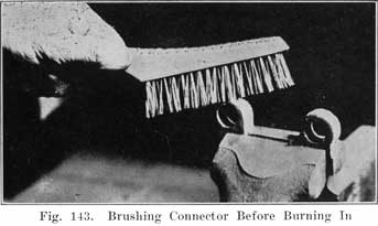
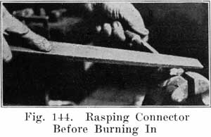
Have the posts perfectly clean and free from acid. Clean the tops, bottoms and sides of the connectors with a wire brush, Figure 143. Finish the top surfaces with a coarse file, Figure 144. With a pocket knife clean the inside surfaces of the connector holes.
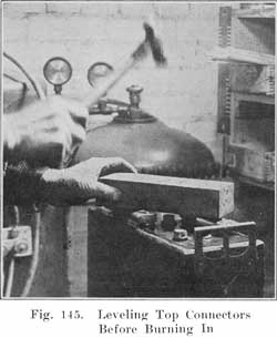
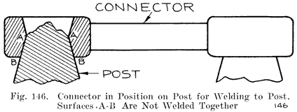
Place the connectors and terminals in their proper positions on the posts, and with a short length of a two by two, two by one, or two by four wood pound them snugly in position, Figure 145. Be sure that the connectors are perfectly level and that the connectors are in the correct position as required on the car on which the battery is to be used. The top of the post should not come flush with the top of the connector. Note, from Figure 146, that the connector has a double taper, and that the lower tapered surface is not welded to the post. If the post has been built up too high it should be cut down with a pair of end cutting nippers so that the entire length of the upper taper in the connector is in plain sight when the connector is put in position on the post. This is shown in Figure 146. With the connectors in place, and before welding them to the posts, measure the voltage of the whole battery to be sure that the cells are properly connected, as shown by the voltage reading being equal to two times the number of cells. If one cell has been reversed, as shown by a lower voltage reading now is the time to correct the mistake.
|
|
|
The connectors and terminals are now ready to be welded to the posts. Before bringing any flame near the battery be sure that you have blown out any gas which may have collected under the covers. Then cover the vents with asbestos or a wet cloth. as, already described. You will need strips of burning lead, such as those made in the burning lead mould described on page 164.Use a hot, hissing flame for the first stage. With the flame properly adjusted, hold it straight above the post, and do not run it across the top of the battery. Now bring the flame straight down over the center of the post, holding it so that the end of the inner cone of the flame is a short distance above the post. When the center of the post begins to melt, move the flame outward with a circular motion to gradually melt the whole top of the post, and to melt the inner surface of the hole in the connector. Then bring the lower end of your burning lead strip close to and over the center of the hole, and melt in the lead, being sure to keep the top of the post and the inner surface of the hole in the connector melted so that the lead you are melting in will flow together and unite. Melt in lead until it comes up flush with the upper surface of the connector. Then remove the flame. This completes the first stage of the welding process. Now repeat the above operation for each post and terminal.
It is essential that the top of the post and the inner surface of the hole in the connector be kept melted as long as you are running in lead from the strip of burning lead. This is necessary to have all parts fuse together thoroughly. If you allow the top of the post, or the inner surface of the hole in the connector to chill slightly while you are feeding in the lead, the parts will not fuse, and the resuilt will be a poor Joint, which will heat up and possibly reduce the current obtained from the battery when the starting switch is closed. This reduction may prevent the starting motor from developing sufficient torque to crank the engine.
When the joint cools, the lead will shrink slightly over the center of the posts. To finish the welding, this lead is to be built up flush or slightly higher than the connector. Brush the tops of the post and connector thoroughly with a wire brush to remove any dirt which may have been floating in the lead. (Dirt always floats on top of the lead.) Soften the burning flame so that it is just barely beginning to hiss. Bring the flame down over the center of the post. When this begins to melt, move the flame outward with a circular motion until the whole top of post and connector begins to melt and fuse. If necessary run in some lead from the burning lead strip. When the post and connector are fused, clear to the outer edge of the connector, raise the flame straight up from the work.
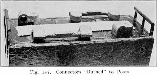
You will save time by doing the first stage of the burning on all posts first, and then finish all of them. This is quicker than trying to complete both stages of burning on each post before going to the next post. The object in the finishing stage is to melt a thin layer of the top of post and connector, not melting deep enough to have the outer edge of the connector melt and allow the lead to run off. All this must be done carefully and dexterously to do a first-class job, and you must keep the flame moving around over the top and not hold it in any one place for ally length of time, so as not to melt too deep, or to melt the outer edge and allow the lead to run off and spoil the job. Sometimes the whole mass becomes too hot and the top cannot be made smooth with the flame. If this occurs wait until the connector cools, soften the flame, and try again. Figure 147 shows the welding completed.
Burning Plates to Strap and Post
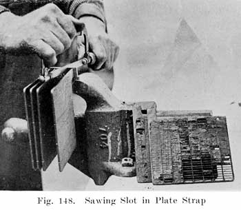
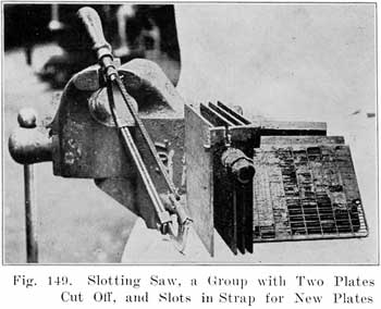
First clean all the surfaces which are to be welded together. Take your time in doing this because you cannot weld dirty surfaces together.Plates which compose a group are welded to a "strap" to which a post is attached, as shown in Figure 5. The straps shown in Figure 5 are new ones, as made in the factory. Plate lugs are set in the notches in the straps and each one burned in separately. In using old straps from a defective group, it is best to cut the strap close to the post, thus separating all the plates from the post in one operation, as was done with tile post shown in Figure 96. If only one or two plates are to be burned on, they are broken or cut off and slots cut in the strap to receive the lugs of tile new plates, as shown in Figures 148 and 149.
Set the plates in a plate burning rack, as shown in Figure 96, placing the adjustable form around the lugs and strap as shown in this figure. Be sure to set the post straight, so that the covers will fit. A good thing is to try a cover over the post to see that the post is set up properly. The post must, of course, be perpendicular to the tops of the plates. If the slotted plate strap shown in Figure 5 is used, or if one or two plates have been cut off, melt the top of the lug of one of the plates which are to be burned oil, and the surfaces of the strap to which the plate is to be welded. Melt in lead from a burning-lead strip to bring the metal up flush with the surface of the strap. Proceed with each plate which is to be burned on.If all the plates have been sawed from the strap, leaving the post with a short section of the strap attached, as shown in Figure 96, melt the edge of the strap, and the top of one or two of the end plate lugs and run in lead from the burning strip to make a good joint. Proceed in this way until all the lugs are joined to the strap and then run the flame over the top of the entire strap to make a smooth uniform weld. Be sure to have the lower edge of the strap fuse with the plate lugs and then run in lead to build the strap up to the proper thickness. Raise the flame occasionally to see that all parts are fusing thoroughly and to prevent too rapid heating.
When enough lead has been run in to build the strap tip to the correct thickness and the plate lugs are thoroughly fused with the strap, raise the flame straight up from the work. Allow the lead to "set" and then remove the adjustable form and lift the group from the burning rack. Turn the group up-side-down and examine the bottom of the strap for lead which ran down the lugs during the welding process. Cut off any such lead with a saw, as it may cause a short-circuit when the plates are meshed with the other group.
In drilling down through the inter-cell connectors to separate them from the posts in opening a battery, the posts may be drilled too short. In reassembling the battery it is then necessary to build the posts up to their original height. This is done with the aid of post-builders, shown in Figure 100.Clean the stub of the post thoroughly and also clean the inside of the post builder. Then set the post builder carefully over the stub post, so that the upper surface of the post builder is parallel to the upper surface of the plate strap. The built up post will then be perpendicular to the surface of the strap, which is necessary, in order to have the covers and connectors fit properly.
With the post builder set properly adjust the burning torch to get a sharp, hissing flame. Bring the flame straight down on the center of the post stub. When the center of the post stub begins to melt, move the flame outward with a circular motion until the whole top of the stub begins to melt. Then run in lead from a burning lead strip, Figure 101, at the same time keeping the flame moving around on the top of the post to insure a good weld. In this way build up the post until. the lead comes up to the top of the post builder. Then lift the flame straight up from the post. Allow the lead to set, and then remove the post builder, grasping it with a pair of gas or combination pliers and turn the post builder around to loosen it.
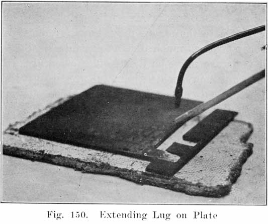
It sometimes happens that a good plate is broken from a strap, thus shortening the lug. Before the plate may be used again, the lug must be extended to its original length. To do this, clean the surfaces of the lug carefully, lay the plate on a sheet of asbestos, and place an iron form having a slot of the correct width, length, and thickness, as shown in Figure 150. Use a medium hissing flame, and melt the upper edge of the lug, and then run in lead from the lead burning strip to fill the slot in the iron form. The plate may then be used again.
Making Temporary Charging Connections
After a battery has been opened it is often desired to charge a battery without burning on the intercell connectors. Temporary connections may be made between cells by placing a short length of a burning lead strip from post to post and applying a flame for an instant to spot-weld the strip to the top of the post.
In using special moulds for casting inter-cell connectors, plate straps with posts, terminals, etc., follow the special instructions furnished by the manufacturers as to the manipulation of the special moulds made by them.Aside from the special instructions for the use of moulds, there are general rules for the melting of lead and handling it after it is melted, which must be observed if good castings are to be made.
Raw Materials. In every battery repair shop a supply of old terminals, cell connectors, posts, and straps, will gradually accumulate. These should not be thrown away or sold as junk, but should be kept in a box or jar provided for that purpose. Old plates should not be saved, since the amount of lead in the grid is small and it is often covered with sulphate. The lugs connecting the plates to the straps may, however, be used. Before using the scrap lead as much dirt as possible should be brushed off, and all moisture must be dried off thoroughly. Scrap lead contains some antimony, which is metal used to give stiffness to tile parts. Using miscellaneous scrap sometimes gives castings which do not contain the proper percentage of antimony. If there is too much antimony present, cracked castings will be the result. To remedy this condition, bars of pure lead should be purchased from some lead manufacturing company. Adding pure lead will reduce the percentage of antimony. Bars of pure antimony should also be kept oil hand in case the castings are too soft.
Lead Melting Pots are standard articles which may be purchased from jobbers. A pot having a 25 pound capacity is suitable for small shops and for larger shops a 125-pound size is best. Before melting any lead in such pots, have them thoroughly free from dirt, grease, or moisture, not merely in order to get clean castings, but also to avoid melted lead being thrown out of the pot on account of the presence of moisture. Severe burns may be the result of carelessness in this respect.
In starting with an empty melting pot, turn oil the heat before putting in any lead, and let the pot become thoroughly heated in order to drive off any moisture. With the pot thoroughly hot, drop in the lead, which must also be dry. When the metal has become soft enough to stir with a clean pine stick, skim off the dirt and dross which collects on top and continue heating the lead until it is slightly yellow oil top. Dirt and lead do not mix, and the dirt rises to the top of the metal where it may readily be skimmed off.
With a paddle or ladle, drop in a cleaning compound of equal parts of powdered rosin, borax, and flower of sulphur. Use a teaspoonful of this compound for each ten pounds of metal, and be sure that the compound is absolutely dry. Stir the metal a little, and if it is at the proper temperature, there will be a flare, flash, or a little burning. A sort of tinfoil popcorn effect will be noticed oil top of the lead. Stir until this melts down.
Have the ladle with which you dip up the melted lead quite dry. When dipping up some of the lead, skim back the dark skin which forms oil top of the lead and dip up the clean bright lead for pouring.
In throwing additional lead into a pot which is partly filled with melted lead, be sure that the lead which is thrown in the pot is dry, or else hot lead may be spattered in your face.
Have the moulds clean and dry. The parts with which the lead comes into contact should be dusted with a mould compound which fills in the rough spots in the metal so that the flow of lead will not be obstructed, and the lead will fill the mould quickly. Dip tip enough lead to fill the part of the mould you use. When you once start pouring do not, under any circumstance, stop pouring until the lead has completely filled the mould. Lead cools very quickly after it is poured into the mould, and if you stop pouring even for all instant, you will have a worthless casting.
In a shop having an ordinary room temperature, it is generally unnecessary to heat the moulds before making up a number of castings. If it is found, however, that the first castings are defective due to the cold mould chilling the lead, the mould should be heated with a soft flame. After a few castings have been made, the mould will become hot enough so that there will be no danger of the castings becoming chilled.
When the castings have cooled sufficiently to be removed, strike the mould a few blows with a wooden mallet or a rawhide hammer to loosen, the castings before opening the mould. The castings may then be removed with a screwdriver.
Cracked castings indicate that the mould was opened before the castings had cooled sufficiently, or that there is too much antimony in the castings. The remedy is to let the castings cool for a longer time, or to add pure lead to the melting pot.
The electrolyte used in the battery is made by mixing chemically pure concentrated Sulphuric Acid with chemically pure water. The concentrated acid, or "full strength" acid cannot be -used, not only because it would destroy the plates, but also because water is needed for the chemical actions which take place as a cell charges and discharges. The water therefore serves, not only to dilute the acid, but also to make possible the chemical reactions of charge and discharge.The full strength acid has a specific gravity of 1.835, and is mixed with the water to obtain the lower specific gravity which is necessary in the battery. The simplest scheme is to use only 1.400 specific gravity acid. This acid is used in adjusting the specific gravity of a battery on charge in case the specific gravity fails to rise to a high enough value. It is also used in filling batteries that have been repaired.
Acid is received from the manufacturer in ten gallon glass bottles enclosed in wooden boxes, these being called "carboys." Distilled water comes in similar bottles. When distilled in the shop, the water should be collected in bottles also, although smaller ones may be used.
Neither the acid nor the water should ever be placed in any vessels but those made of lead, glass, porcelain, rubber, or glazed earthenware. Lead cups, tanks, and funnels may be used in handling electrolyte, but the electrolyte must not be put in containers made of any metal except lead. Lead is rather expensive for making such containers, and the glass bottles, porcelain, rubber, or glazed earthenware may be used.
In mixing acid with water, pour the water in the bottle, pitcher. or jar, and then add the acid to the water very slowly. Do not pour the acid in quickly, as the mixture will become very hot, and may throw spray in your face and eyes and cause severe burns. Never add the water to the acid, as this might cause an explosion and burn your face and eyes seriously. Stir the mixture thoroughly with a wooden paddle while adding the acid. A graduate, such as is used in photography, is very useful in measuring out the quantities of acid and water. The graduate may be obtained in any size up to 64 ounces, or two quarts. In using the graduate for measuring both acid and water, be sure to use the following table giving the parts of water by volume. Although the graduate is marked in ounces, it is for ounces of water only. If, for instance, the graduate were filled to the 8 ounce mark with acid, there would be more than eight ounces of acid in the graduate because the acid is heavier than the water. But if the proportions of acid and water are taken by volume, the graduate may be used.
A convenient method in making up electrolyte, is to have a16 ounce graduate for the acid, and a 32 or 64 ounce graduate for the water. In the larger graduate pour the water up to the correct mark. In the 16 ounce graduate, pour 1.400 acid up to the 10 ounce mark. Then add the acid directly to the water in the graduate, or else pour the water into a bottle or pitcher, and add the acid to that. For instance, if we have a 32 ounce graduate, and wish to make up some 1.280 acid, we fill this graduate with water up to the 5-1/2 ounce mark. We then fill the 16 ounce graduate with 1.400 acid up to the 10 ounce mark. Then we slowly pour the 1.400 acid into the graduate containing the water, giving us 1.280 acid. In a similar manner other specific gravities are obtained, using the same amount of 1.400 acid in each case, but varying the amount of water according to the figures given in the last column of the next to the last table.
The following table shows the number of parts of distilled water to one part of 1.400 specific gravity electrolyte to prepare electrolyte of various specific gravities. The specific gravity of the mixture must be taken when the temperature of the mixture is 70° F. If its temperature varies more than 5 degrees above or below 70°F, make the corrections described on page 65 to find what the specific gravity would be if the temperature were 70° F.
BY WEIGHT
For 1.300 specific gravity use 5 ounces of distilled water for each pound of 1.400 electrolyte.For 1.280 specific gravity use 6-1/2 ounces of distilled water for each pound of 1.400 electrolyte.
For 1.275 specific gravity use 6-3/4 ounces distilled water for each pound of 1.400 electrolyte.
For 1.260 specific gravity use 7-1/2 ounces distilled water for each pound of 1.400 electrolyte.
BY VOLUME
For 1.300 specific gravity use 3-1/2 pints distilled water for each gallon of 1.400 electrolyte.For 1.280 specific gravity use 4-1/2 pints distilled water for each gallon of 1.400 electrolyte.
For 1.275 specific gravity use 5 pints distilled water for each gallon of 1.400 electrolyte.
For 1.260 specific gravity use 5-1/4 pints distilled water for each gallon of 1.400 electrolyte.
In case you wish to use other measuring- units than those given in the above table, this table may be written as follows, giving the number of parts distilled water to 10 parts of 1.400 specific gravity electrolyte:
|
Specific Gravity Desired |
Parts by Weight |
Parts by Volume |
|
1.300 |
3 |
4-1/4 |
|
1.280 |
4 |
5-1/4 |
|
1.275 |
4-1/6 |
6 |
|
1.260 |
4-7/10 |
6-1/2 |
The next table gives the number of parts of distilled water to 10 parts of concentrated sulphuric acid (which has a specific gravity of 1.835) to prepare electrolyte of various specific gravities:
|
Specific Gravity Desired |
Parts by Weight |
Parts by Volume |
|
1.400 |
8-1/2 |
15-8/10 |
|
1.300 |
13-1/2 |
25 |
|
1.280 |
15 |
27 |
|
1.270 |
16 |
28 |
|
1.260 |
17 |
30 |
PUTTING NEW BATTERIES INTO SERVICE
New batteries are received (a) fully charged and ready for service, (b) fully assembled with moistened plates and separators, but without electrolyte, (c) in a "knockdown" condition, with dry plates and without separators, (d) fully assembled with "bone dry" plates and rubber separators, and without electrolyte.Those received fully charged should be put on a car as soon as possible. Otherwise they will grow old on the shelf. Every month on the shelf is a month less of life. If the battery cannot be sold, put it into dry-storage. Batteries received in condition (b) should not be kept in stock for more than six months. Batteries received with dry plates and without separators or with rubber separators may be stored indefinitely without deteriorating.
Batteries Shipped Fully Charged, or "Wet." All Makes
Unpack the battery, keeping the packing case right side up to avoid spilling electrolyte.Brush off all excelsior and dirt, and examine the battery carefully to see if it has been damaged during shipment. If any damage has been done, claim should be made against the express or railroad company.
1. Remove the vent caps from the cells and determine the height of the electrolyte. It should stand from three-eighths to one-half inch above the tops of the plates. The level may be determined with a glass tube, as shown in Fig. 30. If the electrolyte is below the tops of the plates, it has either been spilled, or else there is a leaky jar. If all cells have a low level of electrolyte, it is probable that the electrolyte has been spilled.
2. Next measure the specific gravity of the electrolyte of each cell with the hydrometer, and then add water to bring the electrolyte up to the correct level, if this is necessary. Should the temperature of the air be below freezing, charge the battery for an hour if water is added no matter what the specific gravity readings are. This will cause the water to mix thoroughly with the electrolyte. If the battery were not charged after water is added, the water, being lighter than the electrolyte, would remain on top and freeze. For this one hour charge, use the "starting" rate, as stamped on the nameplate.
3. If the specific gravity of the electrolyte reads below 1.250, charge the battery until the specific gravity reads between 1.280 and 1.300. For this charge use the normal bench charging rates.
4. After this charge place the battery on a clean, dry spot for twenty-four hours as an extra test for a leaky jar. If there is any dampness under the battery, or on the lower part of the battery case, a leaky jar is indicated. An inspection of the level of the electrolyte, which even though no dampness shows, will show the leaky jar.
5. Just before putting the battery on the car, make the high rate discharge test on it. See page 266.
BATTERIES SHIPPED "DRY"
Exide Batteries
Storing. 1. Keep the battery in a dry, clean place, and keep the room temperature above 32 degrees, and below 110 degrees Fahrenheit.2. Put the battery into service before the expiration of the time limit given on the tag attached to the battery. The process of putting the battery into service will require about five days.
3. If the battery has been allowed to stand beyond the time limit, open up one of the cells just before beginning the process necessary to put the battery into service. If the separators are found to be cracked, split, or warped, throw away all the separators from all the cells and put in new ones. If the separators are in good condition, reassemble the cell and put the battery into service.
Putting Battery into Service. 1. Fill the cells with electrolyte of the correct specific gravity. To do this, remove the vent plugs and pour in the electrolyte until it rises to the bottom of the vent tubes. The correct specific gravities of the electrolyte to be used are as follows:
(a) For Types DX, XC, XE, XX and XXV, use 1.360 electrolyte. In tropical countries use 1.260 electrolyte.
(b) For Types LX, LXR, LXRE, LXRV, use 1.340 electrolyte. In tropical countries use 1.260 electrolyte.
(c) For Types MHA and PHC, use 1.320 electrolyte. In tropical countries use 1.260 electrolyte.
(d) For Types KXD and KZ, use 1.300 electrolyte. In tropical countries use 1.240 electrolyte.
2. After filling with the electrolyte, allow the battery to stand ten to fifteen hours before starting the initial charge. This gives the electrolyte time to cool.
3. No sooner than ten to fifteen hours after filling the battery with electrolyte, add water to bring the electrolyte up to the bottom of the vent tubes, if the level has fallen. Replace the vent caps and turn them to the right.
Start charging at the rates shown in the following table. Continue charging at this rate for at least 96 hours (4 days).
Table of Initial and Repair Charging Rates
TYPE AND SIZE OF CELL
Charging Rate-
Amperes
Minimum
Ampere Hours
1/2
50
1-1/2
145
2
190
2-1/2
240
3
290
4
385
4-1/2
430
5
480
5-1/2
525
6
575
6
575
6-1/2
625
7
675
7-1/2
720
4. Occasionally measure the temperature of the electrolyte. Do not allow the temperature to rise above 110° Fahrenheit (120° Fahrenheit in tropical countries). Should the temperature reach 110°, stop the charge long enough to allow the temperature to drop below 100°.
5. At the end of the charge, the specific gravity of the electrolyte should be between 1.280 and 1.300 (1.210 and 1.230 in tropical countries). If it is not between these limits adjust it by drawing off some of the electrolyte with the hydrometer and replacing with water if the specific gravity is too high, or with electrolyte of the same specific gravity used in filling the battery, if the specific gravity is too low.
6. Wipe off the top and sides of the battery case with a rag dampened with ammonia to neutralize any electrolyte which may have been spilled.
7. Just before putting the battery into service, give it a high rate discharge test. See page 266.
1. Remove vent caps from each cell and fill with electrolyte of 1.300 specific gravity. This electrolyte should not have a temperature greater than 75° Fahrenheit when added to the cells.2. After the addition of this acid, the battery will begin to heat and it should be left standing from 12 to 24 hours or until it has cooled off.
3. Battery should then be put on charge at the finish charging rate stamped on the name plate. Continue charging at this rate for approximately 48 to 72 hours or until the gravity and voltage readings of each cell stop rising.
4. Care should be taken to see that the temperature of battery does not rise above 110° Fahrenheit. If this occurs., the charging rate should be cut down.
5. The acid in each cell will undoubtedly have to be equalized.
6. At the finish of this developing charge the gravity should read 1.280 in each cell. If below this, equalize by putting in 1.400 specific gravity acid, or if the contrary is the case and the acid is above 1.280 add sufficient distilled water until the gravity reads 1.280.
7. After the acid has been equalized and it has stopped rising in density the voltage of each cell while still on charge at the finishing rate should read at least 2.5 volts per cell or better.
8. The battery is then ready for service. Just before putting battery into service, make a high rate discharge test on it. See page 266.
Philadelphia Diamond Grid Batteries
1. Remove the vent plugs and immediately fill the cells With electrolyte until the level is even with the bottom of the vent tube in the cover. Do not fill with electrolyte whose temperature is above 90° Fahrenheit. The specific gravity of the electrolyte to be used in starting batteries varies with the number of plates in each cell, the correct values being as follows:
Charging Rates
Fill batteries listed in Table No. 1 with 1. 270 sp. gr. acid.
TABLE -NO. 1
No. of Plates
LL-LLR
and LH
LM
LMR
LT
LTR
LS
LSR
LG
ST
LSF
9
2.0
2.5
2.0
2.5
3.0
11
2.5
3.0
2.5
3.5
4.0
13
3.0
3.5
3.0
4.0
2.5
15
3.5
4.0
3.5
4.5
5.5
17
4.0
5.0
4.0
5.5
6.0
19
4.5
5.5
4.5
6.0
Special Battery: 136 USA................6. 0 amps.
TABLE N0.2
No. of Plates
LL-LLR
and LLH
LM
LMR
LT
LTR
LS
LSR
S
SH
ST
LSF
5
1.0
1.0
2.0
1.5
7
1.5
1.5
1.5
2.0
3.0
2.0
1.5
9
4.0
11
5.0
Special Batteries: 330 AA............. 1. 0 amps.
524 STD-H2 ............ 1. 0 amps.
7 6 SPN ............ 1. 5 amps.
The number of plates per cell is; indicated in the first numeral of the type name. For instance, 712 LLA-1 is a 7 plate LL. For all lighting batteries, types S and ST. use 1.210 electrolyte.
2. Allow the battery to stand for one or two hours.
3. Remove the seal from the top of the vent caps, and open by blowing through the cap.
4. Insert vent plugs in the vent tubes.
5. Put the battery on charge at the rate given in the table on page 228. To determine the rate to use, see type name given on the battery nameplate and find correct rate in the table. Keep the battery charging at this rate throughout the charge.
6. Continue the charge until the battery voltage and the specific gravity of the electrolyte stop rising, as shown by readings taken every four hours. From three and one-half to four days of continuous charging will be required to fully charge the battery.
7. Watch the temperature of the electrolyte, and do not allow it to rise above 110° Fahrenheit. If the temperature rises to 110° F., stop the charge and allow battery to cool. Extend the time of charging by the length of time required for the battery to cool.
8. After the specific gravity of the electrolyte stops rising, adjust the electrolyte to a specific gravity of 1.280 at a temperature of 70° Fahrenheit. If the temperature is not 70°, make temperature corrections as described on page 65.
9. The battery is now ready to be installed on the car. Just before installing the battery, make a high rate discharge test on it.
A Willard Threaded Rubber insulated battery is shipped and carried in stock "bone-dry." It is filled with electrolyte and charged for the first time when being made ready for delivery.Threaded Rubber Insulated Batteries received bone-dry must be prepared for service, as follows:
1. Mix electrolyte to a density of 1.275.
2. Remove the vent plugs and fill to the top of the vent hole with 1.275 electrolyte. Be sure that the electrolyte is thoroughly mixed by stirring and that its temperature is not above 90 degrees Fahrenheit.
3. A portion of the solution will be absorbed by the plates and insulation because they have been standing dry without In-\ liquid in the cells. The volume is thus decreased, necessitating the addition of electrolyte after first filling.
Wait five minutes and then again fill to the top of the vent hole with 1.275 electrolyte.
4. The battery must now stand at least twelve hours and not more than twenty-four hours before charging,. After it has been filled an increase in temperature of the battery solution will take place. This is caused by the action of the acid in the solution penetrating the plates mid reacting with the active material, but does no injury. Since the acid in the solution joins the active material in the plates the density of the solution becomes proportionately lower. This is to be expected and should cause no concern.
In order that the entire plate volume of active material may be in chemical action during charge, the battery should stand before being placed on charge -until the solution has bad time to penetrate the entire thickness of the plates. This requires at least twelve hours, but not more than twenty-four hours.
5. Just before charging the battery, again fill with 1.275 electrolyte to 3/8 inch over the top of the separators. After this, do not add anything but distilled water to the battery solution.
6. The battery should then be put on charge at the finish rate until the gravity stops rising. At the end of this period the specific gravity should be between 1.280 and 1.300. It may take from 36 to 72 hours before this density is reached.
Care should be taken not to prolong the charging unduly, for that may cause active material to fall out of the grids, thus injuring the plates beyond repair.
7. Because of the evaporation of water in the solution during the charging process, it is necessary to add distilled water from time to time in order to keep the solution above the tops of the separators.
The temperature of the battery while on charge should never exceed 110 degrees Fahrenheit. If the temperature rises above this point the charging must be discontinued for a time or the rate decreased.
If at any time during the initial charging the density rises above 1.300 some of the solution should immediately be drawn off with a syringe and distilled water added. This must be done as often as is necessary to keep the density below 1.300.
If the specific gravity does not change after two successive readings and does not then read within the limits of 1.280 to 1.300 it should be adjusted to read correctly. If the reading is less than 1.280 it should be adjusted by drawing off as much solution as can be taken out with a syringe and electrolyte of 1.400 specific gravity added. The battery must then be placed on charge for at least four hours and another reading taken. If it is again found to be less than 1.280 this operation should be repeated as many times as necessary to bring the density up to 1.280.
9. The height of solution when taking the battery off charge should be 5/8 of an inch above the top of the separators. After the battery has been off charge long enough to permit the solution to cool to normal temperature, draw off the excess to a final height of 3/8 inch above separators. Replace the vent plugs and battery is ready for service.
Unfilled Willard Wood Insulated Batteries
Unfilled, wood-insulated batteries have not had an initial charge and require a treatment similar to batteries with threaded rubber insulation. When shipment is made in this manner, such batteries should be placed in service before the date indicated on the tag attached to the battery.To prepare such a battery for service:
1. Remove the vent plugs and fill each cell with 1.335 specific gravity electrolyte (one part of concentrated sulphuric acid by volume to two parts of distilled water by volume) to 3/8 inch above the tops of the separators.
2. Wait 5 minutes and then fill each cell again with 1.335 specific gravity electrolyte to 3/8 inch above the tops of the separators.
3. The battery must then stand from 10 to 15 hours before placing on charge.
4. After standing for this length of time, fill each cell again, if necessary, with 1.335 specific gravity electrolyte to bring the level of the electrolyte 3/8 inch above the tops of the separators before charging.
5. Place the battery on charge at the finish rate marked on the name plate until the gravity and cell voltage stop rising. This charging will require at least 48 hours.
6. If, after a charge of 48 hours or longer the specific gravity does not rise for two consecutive hours, the gravity should be between 1.280 and 1.300. If it is not between these limits, the specific gravity should be adjusted to these values at the end of the charge.
7. If, during the charge, the temperature exceeds 110 degrees Fahrenheit, the charge rate should be reduced so as to keep the temperature below 110 degrees Fahrenheit and the time of charging lengthened proportionately.
Preparing Westinghouse Batteries for Service
(These batteries are prepared for shipment in what is known as export condition.)1. Remove vent plugs and discard soft rubber caps.
2. Fill all cells with 1.300 specific gravity sulphuric acid until top of connecting straps, as seen through vent holes are completely covered. Temperature of filling acid should never be above 90 degrees Fahrenheit.
Note: The aim is to fill the cells with acid of such a Specific gravity that the electrolyte, at the end of charge, will need very little adjusting- to bring it to the proper specific gravity.
1.300 specific gravity acid has been found to be approximately correct for this purpose. However, if after several batteries have been prepared for service -using 1.300 specific gravity acid, considerable adjusting at the end of charge is necessary, it is permissible to use a slightly different specific gravity of filling acid, but the use of acid above 1.325 specific gravity or below 1,250 specific gravity is not recommended.
3. Allow batteries to stand after filling for from two to three hours before putting on charge.
4. Put on charge at finish charge rate shown on name plate of battery.
Note: If temperature of electrolyte in battery reaches 100 degrees Fahrenheit (determined by inserting special thermometer through vent hole in cover), the charging rate should be immediately reduced, as continued charging at a temperature above 100 degrees Fahrenheit is injurious to both separators and plates.
5. Continue charging until all cells are gassing freely and individual cell voltage. and specific gravity of electrolyte have shown no decided rise for a period of five hours.
Note: The length of time required to completely charge a new battery depends largely upon the time the battery has been in stock, varying from twelve to twenty-four hours for a comparatively fresh battery to four or five days for a battery six months or more old.
6. Keep level of electrolyte above tops of separators at all times, while charging by adding distilled water to replace that lost by evaporation.
7. After battery is completely charged the specific gravity of electrolyte in all cells should be adjusted to 1.285 at 70 degrees Fahrenheit, and the level of electrolyte adjusted so that after battery is taken off charge the height of electrolyte stands 1/8 inch above tops of connecting straps.
Note: Corrections for temperature if temperature of electrolyte is above or below 70 degrees Fahrenheit the correction is one point of gravity for each three degrees of temperature. See page 65.
If specific gravity of electrolyte is above 1.285, a portion of the electrolyte should be removed and replaced with distilled water.
If the specific gravity is below 1.285, a portion of electrolyte should be removed and replaced with 1.400 specific gravity sulphuric acid. Acid of higher gravity than 1.400 should never be put in batteries.
Batteries should always be charged for several hours after adjusting gravity to insure proper mixing of the electrolyte and to see that the correct specific gravity of 1.285 has been obtained.
8. After first seven sections have been followed examine vent plugs to see that gas passage is Dot obstructed and screw back in place. Battery is now ready for service.
The Prest-O-Lite Assembled Green Seal Battery
This type of battery is made up of the same sort of plates as the old partly assembled green seal battery. The elements are, however, completely assembled will wood separators and sealed in the jars and box in the same manner as a wet battery to be put into immediate service; the cell connectors are burned in place.How to Store It. A room of ordinary humidity, one in which the air is never dryer for any reason than the average, should be used to store these batteries. They should be shielded from direct sunlight.
Examine the vents-they should be securely inserted and remain so during the entire storage period.
If these precautions are observed, this type battery may be stored for at least a year.
To Prepare Battery for Use. 1. Prepare sufficient pure electrolyte of 1.300 specific gravity. If during the mixing considerable heat is evolved, allow electrolyte to cool down to 90 degrees Fahrenheit. Never pour electrolyte, that is warmer than 90 degrees Fahrenheit, into cells.
2. Remove the vents and lay them aside until the final charging operation has been completed.
Within 15 minutes from the time the vents are removed fill all cells to the bottom of vent openings with the electrolyte prepared, as stated above.
3. Allow the electrolyte to remain in the cells, not less than one hour. At the end of this time, should the electrolyte level fall below the tops of the separators, add enough electrolyte to bring level at least one-half inch above separators. If the temperature in the cells does not rise above 100 degrees Fahrenheit, proceed immediately (before two hours have elapsed) with the initial charging operation. If the temperature remains above 100 degrees Fahrenheit, allow the battery to stand until the electrolyte cools down to 100 degrees Fahrenheit. Then proceed immediately with the charge. It is important that the acid does not stand in the cells for more than two hours, unless it is necessary to allow the acid to cool.
4. Initial Charging Operation. Place the battery on charge at the ampere rate given in the following table. The total initial charge must be for fifty-two hours, but at no time permit the electrolyte temperature to rise above 115 degrees Fahrenheit. If the temperature should reach 115 degrees Fahrenheit, take the battery off the line and allow the electrolyte to cool, but be sure that the total of fifty-two hours actual charging at the ampere rate specified is completed.
Type of Plate
Plates
per Cell
AHS
WHN
RHN
SHC
BHN
JFN
GM
CLN
KPN
3
1.5
5
2
2
2.5
3
7
3
3
3.5
4
3
5
9
4
4
5
5
7
11
5
5
6
7
7.5
5
9
13
6
6
7
8
9
6
10.5
10.5
15
7
7
9
9.5
10.5
7
12
17
10
12
9
19
9
9
11
12
9
The nominal battery voltage and the number of plates per cell is indicated by the Prest-O-Lite type designations, i. e.: 613 RHN denotes 6 volts, 13 plates per cell or 127 SHC denotes 12 volts, 7 plates per cell.
5. The electrolyte density at the end of fifty-two hours charge should be near 1.290 specific gravity. A variation between 1.285 and 1.300 is permissible. If, after fifty hours of the initial charge, the electrolyte density of any of the cells is outside these limits, adjustment should be begun while still charging. For those cells in which the density is higher than 1.300 specific gravity replace some of the electrolyte with distilled water. In those cells where the density is lighter than 1.285 specific gravity replace some -of the electrolyte with previously prepared electrolyte of 1.400 specific gravity. Wait until the cells have charged one hour before taking readings to determine the effect of adjustment, which, if not accomplished, should be attempted again as before. Practice Will enable the attendant to estimate the amount of electrolyte necessary to replace in order to accomplish the proper density desired-at the end of initial charge.
6. Following the completion of the fifty-two hour charge, if there is time to do so, it is good practice to put the battery through a development cycle, i. e., to discharge it at about the four-hour rate and then put it on the charging line again at the normal rate until a condition of full charge is again reached. The objects gained by this discharge are:
(a) Further development of the plates.(b) Adjustment or stabilization of the electrolyte.
(c) Checking the assembly by noting the failure of any cell or cells to act uniformly and satisfactorily during discharge.
The four-hour discharge rate is, of course, like the normal rate of Initial Charge, dependent upon the size and number of plates per cell in any particular battery; the number of cells determines the voltage only and has nothing to do with the battery's charge or discharging rating. These four-hour discharge rates are as follows:
Type of Plate
Plates
per Cell
AHS
WHN
RHN
SHC
BHN
JFN
GM
CLN
KPN
3
3
5
5
5
5.5
6.5
7
7.5
7.5
8
10
7.5
13.5
9
10
10
11
13
18
11
12.5
12.5
14
16
19
12.5
22.5
13
15
15
16.5
19.5
22.5
15
27
27
15
17.5
17.5
19
23
26
17.5
31.5
17
22
26
19
22.5
22.5
25
29
22.5
(7?) Immediately at the end of the four-hour discharge, put the battery on the line and charge it at the normal rate prescribed in the Initial Charge rate table until a state of complete charge, as noted by cell voltage and gravity is reached. This charging time should be about sixteen hours.
Any adjustments of electrolyte found necessary at the end of this charging period in the same manner prescribed in paragraph No. 5, for such adjustments made just before the completion of the initial fifty-two hour charge.
8. At the end of the fifty-two hour charge, or, if the Development discharge has been given, at the end of the Development Cycle Charge, replace the vent plugs, wash all exterior surfaces with clean water and dry quickly. The battery is then ready for service.
A battery must be installed carefully on the car if it is to have any chance to give good service. Careless installation of a battery which is in good working order will invariably lead to trouble in a very short time. On the other hand, a properly installed battery is, nine times out of ten, a good working and long lived battery.After you have removed the old battery, scrape all rust and corrosion from the inside of the battery box or compartment in which the battery is placed. This can best be done with a putty knife and wire brush. If you find that electrolyte has been spilled in the box, pour a saturated solution of baking soda on the parts affected so as to neutralize the acid. Then wipe the inside of the box dry and paint it with a good acid proof paint.
Next take out the hold down bolts. Clean them with a wire brush, and oil the threads on the bolt and in the nut to make them work easily. It is very important that this oiling be done, as the oil protects the bolts from corrosion, and to remove the nuts from a corroded bolt is an extremely difficult and aggravating piece of work, often resulting in the bolts being broken. Should such bolts become loose while the car is in use, it is hard to tighten them.
Wooden strips found in the battery box should be thoroughly cleaned and scraped, and then painted with acid proof paint. When you lower the battery into its box, lower it all the way gently. Do not lower it within an inch or so of the bottom of the case and then drop it. This will result in broken jars and plate lugs. Turn the hold downs tight, but not so tight as to break the sealing compound at the ends of the battery, thereby causing electrolyte to leak out, and battery to become a "slopper".
Cables and connectors should be scraped bright with a knife and brushed thoroughly with the wire brush to remove all corrosion. Old tape which has become acid soaked should be removed and the cable or wire underneath cleaned. Before applying new tape, take a small round bristle brush and paint Vaseline liberally over the exposed cable immediately back of the taper terminal. Then cover the Vaseline with tape, which Should be run well back from the terminal. The Vaseline prevents the corrosion of the cable and the tape holds the Vaseline in place. After the tape has been applied, paint it with acid proof paint. Cover the terminals of the battery with Vaseline. Cables must have enough slack to prevent strains from being put on the battery terminals.
By following these directions, you will not only have a properly installed battery, which will have a good chance to give good service, but will have a neat looking job which is most pleasing to the eye of the car owner.
Remove all dirt from the battery and cable terminals and thoroughly clean the surfaces which are to connect together, but do not scrape off the lead coating. Apply a heavy coating of pure Vaseline to these surfaces and tighten the connection perfectly, squeezing out the Vaseline. Then give the whole connection a heavy coating of Vaseline. This is very important in order to prevent connection trouble.
If battery is installed in an enclosing box, be sure that none of the ventilating holes are clogged.
STORING BATTERIES
When a battery is not in active use on a car it should be put into storage. Storage is necessary:1. When a car is to stand idle for a considerable period, such as is the case when it is held for future delivery.
2. When a car is laid up for the winter.
3. When batteries are kept in stock.
Batteries may be stored "wet," i.e., completely assembled and filled with electrolyte, or "dry," i.e., in a dry disassembled condition, without electrolyte. In deciding whether a battery should be stored "wet" or "dry," two things are to be considered, i.e. the length of time the battery is to be in storage, and the condition of the battery. If a battery is to be out of commission for a year or more, it should be put into "dry" storage. If it is to be in storage for less than one year, it may be put into "wet" storage if it is in a good condition. If the condition of the battery is such that it will need to be dismantled soon for repairs, it should be put into "dry" storage, even though it is to be out of service for less than one year.
Batteries in "dry" storage require no attention while they are in storage, but they must be dismantled before being put into storage and reassembled when put back into service.
When a battery is brought in to be stored, note its general condition carefully.
(a) Its General Appearance-condition of case, handles, terminals, sealing compound, and so on.
(b) Height and specific gravity of the electrolyte in each cell.
(c) Age of Battery. Question owner as to length of time he has had battery. Read date marks on battery if there are any, or determine age by the age code. See page 243. If a battery is less than a year old, is in good condition, and is to be stored for less than one year, it may be put into "wet" storage. If it is more than a year old, put it into dry storage, unless it is in first class shape and is to be stored for only several months.
After making your general observations, clean the battery, add distilled water to bring the electrolyte up to the proper level, put the battery on charge and keep it on the line until it is fully charged. Watch for any abnormal condition during the charge, such as excessive temperature rise, failure of voltage to come up, failure of specific gravity to come up, and gassing before gravity becomes constant.
If no abnormal conditions develop during the charge, put the battery on discharge at a rate which will cause the voltage to drop to 1.7 volts per cell in about four hours. Measure the cell voltages at regular intervals during the discharge test. If the voltage of any cell drops much more rapidly than that of the other cells, that cell is defective in some way, and should be opened for inspection. If the voltage of all cells drops to 1.7 in three hours or less, the battery should be put into dry storage.
After completing the discharge test, recharge it fully, no matter whether it is to be put into wet or dry storage.
If no trouble developed during the charge or discharge, the battery may be put into "wet" storage. If trouble did develop, the battery should be put into "dry" storage.
If dry storage is found to be necessary the owner should be informed that the condition of his battery would cause it to deteriorate in wet storage and necessitate much more expensive repairs when put into use again than will be necessary in the thorough overhauling and rejuvenation of dry storage. He should be advised that dry storage involves dismantling, drying out elements and reassembling with the needed repairs and new separators in the Spring. Be sure that the customer understands this. If it is evident that repairs or new parts, involving costs additional to storage charges, will be necessary, tell him so. Do not leave room for a complaint about costs in the Spring.
To avoid any misunderstanding, it is highly advisable to have the customer put his signature on a STORAGE AGREEMENT which states fully the terms under which the battery is accepted for storage. The storage cost may be figured on a monthly basis, or a price for the entire storage period may be agreed upon. The monthly rate should be the same as the regular price for a single battery recharge. If a flat rate is paid for the entire storage period, $2.00 to $3.00 is a fair price.
1. Store the batteries on a bench or shelf in a convenient location and large enough to allow a little air space around each battery.2. Place each battery upon wooden strips in order to keep the bottom of the battery clear of the bench or shelf,
3. Apply Vaseline freely to the battery terminals, and to exposed copper -wires in the battery cables if the cables are burned directly to the battery terminals. If the cables are not burned on, remove them from the battery.
4. If convenient, install the necessary wiring, switches, etc., so that batteries may be connected up and charged where they stand. Otherwise the batteries must be charged occasionally oil the charging bench.
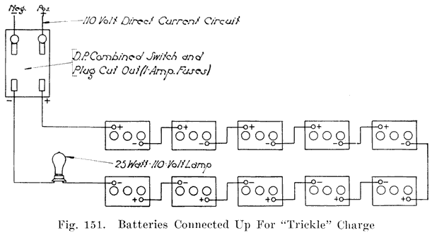
5. Batteries in wet storage may be charged by the Exide "Trickle" charge method, or may be given a bench charge at regular intervals.6. Bench Charge Method.- Once every month, add distilled water to replace evaporation. Then give battery a bench charge. See page 198. Before putting battery into service repeat this process and just before putting the battery into service, make the high rate discharge test on it. See page 266.
7. Trickle Charge Method.- This consists of charging the batteries in storage continuously at a very low rate, which is so low that no gassing occurs, and still gives enough charge to maintain the batteries in good condition. In many cases the "Trickle" Charge method will be found more convenient than the bench charge method, and it has the advantage of keeping the batteries in condition for putting into service on short notice. It should, however, be used only where direct current lighting circuits are available.
In the "Trickle" method, the batteries are first given a complete bench charge, and are then connected in series across a charging circuit with one or several incandescent. lamps in series -with the batteries to limit the current. In Fig. 151, an example of connections for a "Trickle" charge is given. The charging current for different sized batteries varies from 0.05 to 0.15 ampere. The following table gives the lamps required to give the desired current on 110 volt circuit.
In each case, the lamps are connected in series with the batteries. The "2-25 watt, (lamps), in parallel" listed in the table are to be connected in parallel with each other and then in series with the batteries. The same is true of the "3-25 watt (lamps), in series" listed in the table.
Amp. Hours.
Capacity
5 Amp. Rate
Amperes
Approximate
No. of Cells in
Series on Line
115-Volt
No. 115 Volt
Lamps Required
115-Volt
50 or less
0.05
3
50 or less
0.05
30
50 or less
0.05
45
50 - 100
0.10
3
50 - 100
0.10
30
50 - 100
0.10
45
100 or over
0.15
3
100 or over
0.15
30
100 or over
0.15
45
Every two months interrupt the trickle charge long enough to add water to bring the electrolyte up to the proper level. When this has been done, continue the trickle charge.
Before putting the batteries into service, see that the electrolyte is up to the correct level, and that the specific gravity of the electrolyte is 1.280-1.300. If necessary, give a short charge on the charging bench to bring the specific gravity up to the correct value.
1. Give the battery a complete charge. Pour out the electrolyte, and separate the groups. If the negatives have bulged active material, press them in the plate press. In batteries such as the Prest-OLite in which it is difficult to remove the plates from the cover, the groups need not be separated unless the negatives have badly bulged active material. It may not be necessary to separate the groups even then, provided that the positives are not buckled to any noticeable extent. If only a very slight amount of buckling exists, the entire element may be pressed by putting thin boards between the plates in. place of the separators.2. Immerse the negatives in distilled water for ten to twelve hours. If positives and negatives cannot be separated, wash each complete element in a gentle stream of water.
3. Remove plates from water and allow them to drain thoroughly and dry. The negatives will heat up when exposed to the air, and when they do so they should be immersed in the water again to cool them. Repeat this as long as they tend to heat up. Then allow them to dry thoroughly.
4. Throw away the old separators. Rubber separators may be saved if in good condition. Clean the covers and terminals., wash out the jars, and turn the case up side down to drain out the water. Examine the box carefully. It is advisable to wash with a solution of baking soda, rinsing the water in order to neutralize as far as possible the action of acid remaining on the box. If this is not done, the acid may start decomposition of the box while in storage, in which. case the owner of the battery may insist on its renewal before acceptance at the end of the storage period.
5. When, the plates are perfectly dry, nest the positives and negatives together, using dry cardboard instead of separators, and replace them in the jars in their proper positions.
6. Replace the covers and vent plugs, but, of course, do not use any sealing compound on them.
7. Tie the terminals and top connectors to the handle on the case with a wire.
8. Tag the battery with the owner's name and address, using the tag on which you made the sketch of the arrangement of the terminals and top connections.
9. Store the battery in a dry place, free from dust, until called for.
10. When the battery is to be put into service again, put in new separators, put the elements in the jars, seal the covers, and burn on the top connectors and terminals (if these are of the burned-on type). Fill the cells with electrolyte of about 1.310 specific gravity and allow the battery to stand for ten to twelve hours in order to cool. Then put the battery on charge at one-half the normal charging rate and charge until the specific gravity of the electrolyte stops rising and remains stationary for five hours. The total time required for this development charge will be about four days. Watch the temperature of the electrolyte carefully, and if it should rise to 110° Fahrenheit, stop the charge until it cools.
11. The specific gravity will fall during the first part of the charge, due to the new separators; at the end of the charge, the specific gravity should be 1.280-1.300. If it is not within these limits, adjust it by withdrawing some electrolyte with the hydrometer and adding water if the gravity is high, or 1.400 electrolyte if the gravity is low.
12. Clean the case thoroughly and give it a coat of asphaltum paint.
13. Just before putting the battery into service, give it a high rate discharge test. See page 266.
Battery manufacturers use codes to indicate the age of their batteries. These codes consist of letters, figures, or combinations of letters and figures, which are stamped on the inter-cell connectors or on the nameplate. The codes may also be burned on the case.The codes of the leading makes of batteries follow. In addition to determining the age of a battery by means of the code, the owner should be questioned as to the time the battery was installed on his car. If the battery is the original one which came with the car, the dealer's or car manufacturer's records will help determine the battery's age. If a new battery has been installed to replace the one that came with the car, the battery distributor's records will help determine the age of the battery.
Familiarity with the different makes and types of battery will also help in determining a battery's age. Manufacturers make improvements in the construction of. their batteries from time to time, and by keeping up-to-date on battery constructions, it is often possible to approximate the age of a battery by such changes.
If a battery was kept "dry" while in stock, its age should be figured from the time it was prepared for service and placed on the car, since batteries in dry storage do not deteriorate. Some batteries are shipped from the factory "wet," i.e., filled with electrolyte and fully charged and the age of such batteries should be figured from the time they were shipped from the factory, because deterioration begins as soon as a battery is filled with electrolyte. When batteries are "dry" no chemical action can take place, and the battery does not deteriorate, while in a "wet" battery, chemical action takes place which gradually causes a battery to deteriorate.
(Omitted were nine charts and their short descriptions which contained the number/letter date code information ranging from 1918 to 1923 for nine brands of batteries.)
RENTAL BATTERIES
Rental batteries are those which are put on a customer's car while his own is being repaired or recharged. They are usually rebuilt batteries turned in when a new battery is bought. They may also be made of the good parts of batteries which are junked. By carefully saving good parts, such as plates, jars, covers, and cases, a stock of parts will gradually be acquired from which rental batteries may be made. Rental batteries may also be bought from the battery manufacturers.A supply of rental batteries should, of course, be kept ready to go out at any time. The number of such batteries depends upon the size of the business. 25 batteries for each 1000 cars in the territory served is a good average. Do not have too many rental batteries of the same type. Many of them will be idle most of the time and thus will not bring in any money. Rentals should be made to fit those makes of cars of which there are the greatest number in the territory served by the repair shop. Sufficient parts should be kept on hand to make up other rentals on short notice.
Terminals for Rental Batteries
There are several combination terminals on the market which allow rental batteries equipped with them to be easily connected to several of the various types of cable terminals that are in use. Yet it is a universal experience for the average service station always to have calls for rental batteries with just the type of terminals which are not on hand. When the station has many batteries with the clamp type straight posts the call always seems to be for the taper plug type and vice versa.
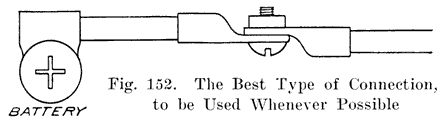
Most of us will agree that the clamp type post terminal is the cause of much trouble. It is almost impossible to prevent corrosion at the positive post and many a car owner has found that this has been his trouble when his lights burn all right but the battery seemingly does not have power enough to turn over the engine and yet every cell tests 1.280. Service Station men should not scrape and clean up a corroded clamp type terminal and put it back on again, but should cut it off and put on either a taper plug or, preferably, a lead-plated copper terminal lug. Of course either of these terminal connections necessitates changing the battery terminals to correspond.For rental batteries it will be found that short cable terminals with lead-plated copper lugs at the end will enable a battery man to connect most any type of cable terminal on any car. It is true that such connections must be taped up, but the prompt service rendered more than offsets a little tape. Figures 152 to 158 illustrate how these connections can be made to the taper plug and clamp types which are used on most cars.
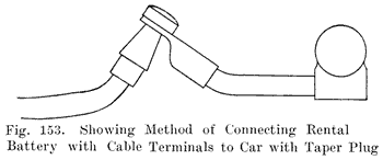
![]()
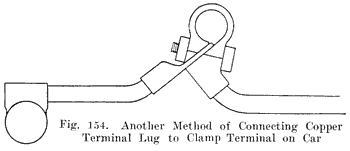
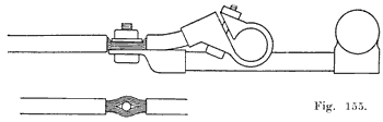
![]()
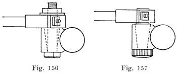
Fig. 155. Showing method of connecting rental batteries with cable terminals, to cars with clamp type terminals. In Fig. 155 the cable insulation is stripped for a space of an inch and the strands are equally divided with an awl. A bolt is passed through the opening and a washer and nut complete the connection. |
Two methods of connecting a clamp type terminal to taper plug terminals. In Fig. 156 a taper plug is inserted and screwed tight. The projecting part of the plug has been turned down to fit the clamp type terminal which is clamped to it. In Fig. 157 a bolt is passed through and the clamp type terminal tightened to the plug type terminal with a washer and nut. |
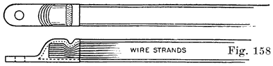
Fig. 158 shows a simple means of putting on a lead-plated copper terminal lug without solder. These lugs should be soldered on whenever possible, but it is often a difficult job to put one on in the confined space of some battery compartments. In such places, a quick and lasting job can be made with a band vise and a short piece of round iron. This latter is laid across the lug and the vise screwed up, making a crimp across the lug which firmly grips down upon the bared cable strands that have been inserted into the lug.New batteries sold to replace other batteries should be installed with cable connections, as illustrated in Figure 152. This method of connecting a battery is superior to any other method and will never cause trouble. It will usually be found that the old taper plugs or clamp terminals that have been in use have started to corrode and that a new battery works increasingly at a disadvantage from the day it is installed until the corrosion becomes so great that the car cannot be started and then the customer kicks about his new battery. The best connection possible will pay handsome dividends to all concerned, in the end.
Marking Rental Batteries. Rental batteries should be marked in a mariner which enables them to be recognized quickly. Painting the cases a red color is a good way. The service station's name should appear somewhere on the battery. A good plan is to have a lead tag, which is attached to the handle at the negative end of the battery, or is tacked to the case. The name may also be painted on the case. Each battery should be given a number which should preferably be painted in large white figures on the end or side of each case. The number may also be stamped on a lead tag tied to the handle at the negative end.
A service station which sells a certain make of battery should not use cases of some other make if the name of the other make appears on the case. Such names may give a wrong impression to the customer, which will not be fair either to the service station or to the manufacturer whose name appears on the case. If the service station sells, another make of battery, the customer may get the impression that the service station man does not have enough confidence in the make which he sells, and must use some other make for his rentals. If the rental battery does not give good service, the customer will get the impression that the manufacturer whose name appears on the case does not turn out good batteries, when as a matter of fact, the plates, covers, jars, and other parts used in the rental battery may not have been made by this manufacturer. Some battery men would, perhaps, consider the failure of a rental battery as an opportunity to "knock" the manufacturer whose name appears on the case. Such an action may have the desired effect on a very few customers, but the great majority of men have no use for any one who "knocks" a competitor's products.
Keeping a Record of Rental Batteries. A careful record should be kept of all rental batteries. The more carefully such a record is kept, the less confusion there will be in knowing just where every rental battery is. A special rack for rental batteries, such as those shown in Figures 88 and 89 should be provided, and all rental batteries which are in the shop should be kept there, except when they are on charge or are being overhauled. Have them fully charged and ready to go out immediately, without keeping a customer waiting around, when he is in a hurry to go somewhere else.
General Rental Policy. No service station should make a practice of installing rental batteries on any car unless the owner leaves his own battery to be repaired or recharged. The purpose of having a stock of rental batteries is to enable customers to have the use of their cars while their own batteries are being repaired by the battery man who furnishes the rental battery and not to furnish batteries to car owners who may be taking their batteries to some other station to be repaired. It is, of course, a good thing to be generous and accommodating, but every battery repairman should think of his own business first, before he helps build up the business of a competitor.
The customer must have some inducement to bring in your rental battery and get his own. A rental charge of 25 cents- per day serves as a reminder to most customers. However, some customers are forgetful and the battery man must telephone or write to any owner who fails to call for his battery. If, due to failure to keep after the owner, a rental battery is out for several weeks, there is likely to be an argument when the rental bill is presented to the owner. If the delay in calling in a rental battery is due to failure to repair the customer's battery, the rental charge should be reduced.
A rental battery should not be put in place of a battery which is almost ready for the junk pile. The thing to do is to sell the customer a new battery. Repairs on an almost worn out battery are expensive and the results may not be satisfactory.
The wide-awake battery man will not overlook the new and rapidly growing field which has been opened for him by the installation of hundreds of thousands of radio-phone receiving sets in all parts of the country. The so-called radio "craze" has affected every state, and every battery repairman can increase his income to a considerable extent by selling, charging, and repairing radio storage batteries.The remarkable growth of the radio-phone has, of course, been due to the radio broadcasting stations which have been established in all parts of the country, and from which concerts, speeches, market reports, baseball reports, news reports, children's stories and religious services are sent out. These broadcasting stations have sending ranges as high as 1,000 miles. The fact that a service station is not located near a broadcasting station is therefore no reason why it should not have its share of the radio battery business, because the broadcasting stations are scattered all over the United States, and receiving sets may be made powerful enough to "pick up" the waves from at least one of the broadcasting stations.
Radio receiving sets may be divided into two general classes, the "Crystal" sets and the "Bulb" sets. "Crystal" sets use crystals of galena (lead sulphide), silicon (a crystalline form of silicon, one of the chemical elements), or carborundum (carbide of silicon) to "detect" or, in other words, to rectify the incoming radio waves so that they may be translated into sound by the telephone receivers. Receiving sets using these crystals do not use a battery, but these sets are not very sensitive, and cannot "pick up" weak waves. This means that crystal receiving sets must be used near the broadcasting stations, before the waves have been weakened by traveling any considerable distance.
As a general rule, the radio-listener's first receiving set uses a crystal detector. Very often it is difficult to obtain good results with such a set, and a more elaborate set is obtained. Moreover, even if a crystal set does give good results, the owner of such a set soon hears of friends who are able to hear concerts sent out from distance stations. This gives him the desire to be able to hear such stations also and he then buys a receiving set which uses the "audion-bulb" for detecting, or rectifying the incoming waves.
The audion-bulb resembles an ordinary incandescent lamp. It contains three elements:
1. In the center of the bulb is a short tungsten filament, the ends of which are brought out to two terminals in the base of the bulb. This filament must be heated to incandescence, and a storage battery is required for this purpose, because it is necessary to have a very steady current in order to obtain clear sounds in the receiver. Lately plans have been suggested for using a direct current lighting line, and even an alternating current lighting line for heating the filament, but at present such plans have not been perfected, and the battery will undoubtedly continue to be used with the majority of sets.
2. Surrounding the filament but not touching it is a helix of wire, only one end of which is brought out to a terminal in the base of the bulb. This helix is called the "grid." In some bulbs the grid is not made in the form of a helix, but is made of two flat gridlike structures, one on each side of the filament.
3. Surrounding the "grid" is the "plate" which is sometimes in the shape of a hollow metallic cylinder. Some plates are not round, but may be oval, or they may be two flat plates joined together at some point, and one placed on either side of the grid. The plate has one terminal in the base of the bulb.
The action of an audion-bulb is quite complex, but a simpler explanation, though one which may not be exactly correct from a purely technical point of view, is as follows, referring to Figure 159: |
|
As long as the filament remains lighted a steady current flows through the above circuit. The "grid" is connected to the aerial wire to intercept the radio waves. These waves produce varying electrical charges on the grid. Since the stream of charged particles emitted by the filament must pass through the grid to reach the plate, the charges which the radio waves produce on the grid strengthen or weaken the stream of electrons emitted by the filament, and thus vary the current flowing in the telephone receiver circuit. The changes in this current cause the receiver diaphragm to vibrate, the vibrations causing sounds to be heard. Since the variation in the telephone receiver circuit is caused by electrical charges produced by the radio waves, and since the radio waves change according to the sounds made at the transmitting station, the variations in the telephone receiver current produces the same sounds that are sent out at the transmitting station. In this way concerts, speeches, etc., are reproduced in the receivers.The modern radio receiving set includes various devices, such as variable condensers, variocouplers, loose-couplers, variometers, the purpose of which is to "tune" or adjust the receiving set to be capable of receiving the radio waves. An explanation of such devices is not within the scope of this book, but there are numerous reasonably priced books and pamphlets on the market which describes in a simple manner all the component parts of a radioreceiving set.
From the foregoing remarks it is seen that a six-volt storage battery is required with each receiving set which uses the audionbulb type detector. The filament current of an audion-bulb averages about one ampere. If additional bulbs are used to obtain louder sounds, each such bulb also draws one ampere from the storage battery. The standard audion-bulb receiving set does not use more than three bulbs, and hence the maximum current drawn from the battery does not exceed three amperes.
The automobile battery manufacturers have built special radio batteries which have thick plates and thick separators to give longer life. The thick plates are much stronger and more durable than the thin plates used in starting and lighting work, but do not have the heavy current capacity that the starting and lighting battery plates have. A high current capacity is, of course, not necessary for radio work, and hence thick plates are used.
Batteries used for radio work do not operate under the severe conditions which exist on automobiles, and trouble is much less likely to develop. However, the owner of the radio set rarely has any means of keeping his battery charged, and his battery gradually discharges and must then be recharged. It is in the sale of batteries for radio work and in the recharging of them that the battery man can "cash-in" on the radio phone "craze."
This business rightfully belongs to the automobile battery man and he should go after it as hard as he can. A little advertising by the service station man, stating that he sells radio batteries, and also recharges them should bring in: very profitable business. The battery man who calls for and delivers the radio batteries which need recharging and leaves rental batteries in their place so that there is no interruption in the reception of the evening concerts is the one who will get the business.
As already stated, radio storage batteries have thick plates and thick separators. Perforated rubber sheets are also used in addition to the separators. Large sediment spaces are also generally provided to allow a considerable amount of sediment to accumulate without causing short-circuits. The cases are made of wood or hard rubber. Since radio batteries are used in homes and are, therefore, used with handsomely finished cabinets containing the radio apparatus, the manufacturers give the cases of some of their radio batteries a pleasing varnished or mahogany finish. Before returning radio batteries which have been recharged, the entire batteries should be cleaned and the cases polished. Returning radio batteries in a dirty condition, when they were received clean, and polished, will drive the radio recharging business to some other service station.
The Vesta Battery Corporation manufacturers three special types of "A" batteries for radio work, as follows:1. The 6EA battery, made in capacities of 60, 80, and 100 ampere hours. Fig. 160.
2. The V6EA7 battery, having a capacity of 80 ampere hours. Fig. 161.
3. The R6EA battery, having a capacity of 100 ampere hours. Fig. 162.
Vesta Radio Batteries. Fig. 160 shows the 6EA Series, "A" Battery. Fig. 161 shows the V6EA Series, "A" Battery. Fig. 162 shows the R6EA (Rubber Case) Series, "A" Battery. Fig. 163 shows the "B" Battery.These batteries have 5, 7, 9 plates per cell, respectively. The plates are each 5 inches high, 5 7/8 inches wide, and 5/32 inches thick. The cases for these batteries are furnished in three designs - plain black boxes (all sizes), finished maple boxes (7 plate size only), and hard rubber boxes (9 plate size only). These Vesta batteries are the "A" batteries used for heating the filaments of the audion bulbs. The Vesta Radio "B" battery, Fig. 163, is a 12 cell, 24 volt battery, with a 22 and a 20 volt tap.
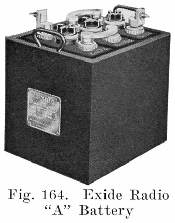
The Exide Radio "A" battery, Fig. 164, is made in four sizes, the capacities ranging from 20 to 120 ampere-hours. The design and construction of these batteries are similar to the Exide starting batteries. The over-all height of these batteries is approximately 95/8 inches, the width 7-5/16 inches, while the length varies with the number of the plates.
|
Type |
Cat. No. |
Length |
Weight |
Capacity |
|
3-LXL-3 |
13735 |
4-9/16 |
15-1/2 lbs. |
20 amp. hrs. |
|
3-LXL-5 |
13736 |
5-11/16 |
24-1/2 lbs. |
40 amp. hrs. |
|
3-LXL-9 |
13737 |
9-1/16 |
42-1/2 lbs. |
80 amp. hrs. |
|
3-LXL-13 |
13750 |
12-7/16 |
59-1/2 lbs. |
120 amp. hrs. |
The Willard Storage Battery Co. manufactures both "A" and "B" storage batteries. The Willard "A" battery, Fig. 165, is an all-rubber battery. The case is a rubber "Monobloc" construction, that is, the entire case is pressed into shape at one time. There are no separate jars for the cells, there being rubber partitions which form integral parts of the case. The case is, therefore, really a solid, one piece, three compartment jar. The ribs at the bottoms of the compartments are parts of the one-piece block, and are higher than those found in the usual starting and lighting battery. Embedded in each side wall of the case is a bronze button which holds the handle in place. Soft rubber gaskets of pure gum rubber surround the post to make an acid proof seal to prevent electrolyte from seeping from the cells. The separators are the standard Willard "Threaded Rubber" separators.

Willard Radio Batteries. Fig. 165 shows the All-Rubber "A" Battery. Fig. 166 shows the complete "B" Battery. Fig. 167 shows one cell of the "B" Battery.The Willard "A" battery comes in five sizes, type WRR97 (20 ampere hours capacity), type WRRO (50 ampere hours capacity), type WRR1 (89 ampere hours capacity), type WRR2 (100 ampere hours capacity), and type WRR3 (125 ampere hours capacity).
The Willard "B" storage battery, type CBR124, Figs. 166 and 167, is a twelve cell battery, each cell consisting of a round glass container having one negative and one positive plate insulated from each other by a small "Threaded Rubber" separator. The plates and separators rest on a hard rubber "bottom rest" which consists of a short length of hard rubber tube, so formed as to support the plates and separators and at the same time hold them together. The cells are assembled in a case which has a separate compartment for each cell. As seen from Fig, 166, the upper parts of the cells project above the top of the case, which simplifies inspection.
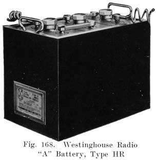
![]()
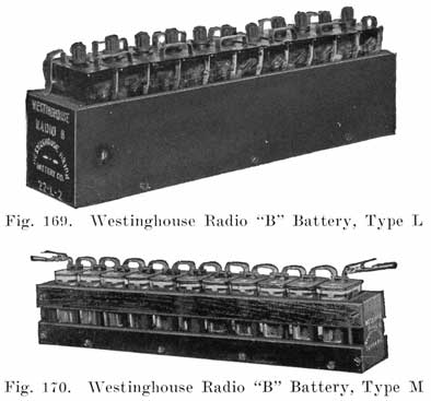
The Westinghouse Union Battery Co. manufactures both "A" and "B" storage batteries. Their "ER" type, Fig. 168, is the "A" battery, and their "L" and "M" types, Figs. 169 and 170, are the "B" batteries. The HR battery has 3/16 inch thick plates, high rests to provide ample mud and acid space, and thick separators. Rubber sheets are placed on both sides of the positive plates. Rubber covered cables are moulded into the terminals to minimize corrosion at the positive terminal. The "HR" batteries are made in six and eight volt sizes, with 3 plates per cell, 5 plates per cell, 9 plates per cell, and 13 plates per cell.The Westinghouse Radio "B" batteries are made in two sizes. Type 22-M-2, Fig. 170, has a capacity of 1.2 ampere hours at 0.04 ampere. It is designed to operate a receiving set having one detector and two amplifier bulbs for three to five weeks between charges. The type 22-L-2 battery, Fig. 169, has a capacity of 4.5 ampere hours at 0.25 ampere.
|
Part No. |
Type |
Volts |
Amp. Hours. at 3 Amps. Intermittent rate. |
Weight |
|
100110 |
6-HR-5 |
6 |
54 A.H. |
30 Lbs. |
|
100111 |
6-HR-9 |
6 |
108 A.H. |
46 Lbs. |
|
100112 |
6-HR-13 |
6 |
162 A.H. |
65 Lbs. |
|
100135 |
8-HR-5 |
8 |
54 A.H. |
40 Lbs. |
|
100136 |
8-HR-9 |
8 |
108 A.H. |
60 Lbs. |
|
100137 |
8-HR-13 |
8 |
162 A.H. |
87 Lbs. |
|
100145 |
6-HR-3 |
6 |
27 A.H. |
20 Lbs. |
|
Part No. |
Type |
Volts |
Capacity |
Weight |
|
100148 |
22-M-2 |
22 |
1.2 A.H. at .04 Amps. |
6-1/4 Lbs. |
|
100140 |
22-L-2 |
22 |
4.5 A.H at .25 Amps |
19-3/4 Lbs. |
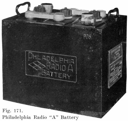
The Philadelphia Storage Battery Co. makes both "A" and "B" Radio batteries. The "A" battery, Fig. 171, uses the standard diamond-grid plates, and the "Philco Slotted Retainer" used in Philadelphia starting batteries. The cases of the "A" batteries are made of hardwood, finished in an ebonite black. Soft rubber insulating feet on the bottom of the case prevent scratching any table or varnished floor on which the battery may be set. The instructions for preparing the Philadelphia "A" battery for service are similar to those given for the. starting and lighting batteries, given on page 228. For the initial filling, 1.220 electolyte is used, and the battery charged at the following rates:
Initial and Recharge Charging Rate
|
Type |
Initial Rate |
Recharge Rate |
|
56LAR |
1.0 |
2 |
|
56RAR |
2.0 |
3 |
|
76RAR |
3.0 |
4.5 |
|
96RAR |
4.0 |
6 |
|
116RAR |
5.6 |
7.5 |
|
136RAR |
6.0 |
9 |
The final gravity of the electrolyte should be 1.250. However, if the owner insists on getting maximum capacity, the battery may be filled with 1.250 electrolyte and balanced to 1.290 at the end of the charge.
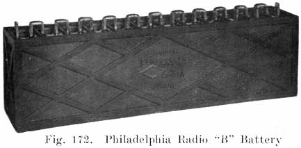
The Philadelphia Radio "B" battery, type 224-RB, Fig. 172, has 12 cells contained in a one-piece rubber case. It is shipped dry, and requires no initial charge. To prepare it for service, the soft rubber vent caps are removed and 25 c. c. of 1.250 electrolyte poured into each cell.
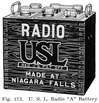
The U. S. L. Radio "A" battery, Fig. 173, uses 1/4 inch positives, with 3/16 inch intermediate and 1/8 inch outside negatives. Port Orford cedar separators are used which are four times as thick as the usual starting battery separator. The case is made of hardwood, and is varnished to match cabinet work. The electrolyte has a specific gravity of 1.220. The heavy plates and separators and the low gravity of the electrolyte are designed to give long life.
|
Type |
Plates per Cell |
Ampere Hour Capacity @ 3 Amperes |
Ampere Hour Capacity @ 1 Amperes (or intermintet use) |
Dimensions |
Weights |
|
DXA-303-X |
3 |
12 |
20 |
5-3/16 x 7-1/4 x 9-1/4 |
18 |
|
DXA-305-X |
5 |
40 |
60 |
9-1/8 x 7-1/4 x 9-1/4 |
39 |
|
DXA-307-X |
7 |
70 |
85 |
11-3/4 x 7-7/16 x 9-1/4 |
48 |
|
DXA-309-X |
9 |
98 |
115 |
14-3/8 x 7-7/16 x 9-1/4 |
59 |
The Prest-O-Lite Co. makes two lines of Radio "A" Batteries. First, an inexpensive battery, Fig. 174, and a deluxe battery, Fig. 175, which has a better finish and appearance. Both types have a mahogany finished case with rubber feet to prevent damaging furniture. A bail handle simplifies the carrying of the battery. Capacities range from 47 ampere-hours to 127 ampere-hours at a one ampere discharge rate.
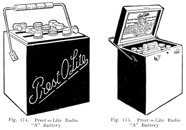
Table of Prest-O-Lite Radio Batteries
|
The Universal Battery Co. manufacture three types of Radio "A" storage batteries. Type WR, Fig. 176, has three sealed hard rubber jars assembled in a hardwood case which is stained and finished in mahogany. The separators are made of Port Orford cedar and are 1/8 inch thick, about twice the thickness of the separator used in starting and lighting batteries. The plates also are much thicker than the standard starting and lighting battery plate. The type WR battery comes in three sizes. Types WR-5, WR-7, and WR-9, having capacities of 60, 85, and 105 ampere hours, respectively, at a 3 ampere rate. |
|
The Universal type RR radio "A" battery, Fig. 177, is assembled in a hard rubber combination case, which is a solid piece of rubber divided into three compartments. This gives a compact, acid proof case. This battery also comes in three sizes, types RR-5, RR-7, and RR-9, having capacities of 60, 85 and 105 ampere hours, respectively, at a three ampere discharge rate.
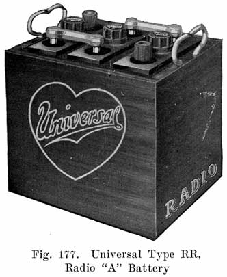
![]()
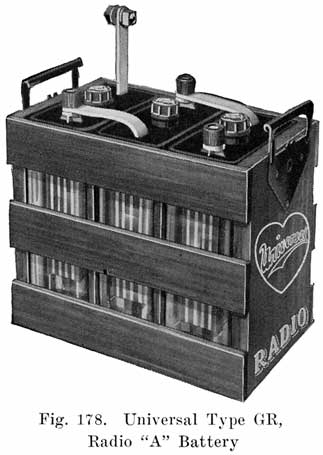
The Universal type GR radio "A" battery, Fig. 178, is assembled in three sealed glass jars which are placed in a mahogany finished wooden crate. This construction makes the cell interiors visible, enabling the owner to detect troubles and to watch the action of the cells on charge and discharge. The GR battery comes in two sizes, GR-5 and GR-Jr., having respective capacities of 60 and 16 ampere hours at a 3 ampere discharge rate.
During the past year or two, so-called "dry" starting and lighting storage batteries have appeared on the market. This class includes batteries having "dry," "semi-dry," and "jelly" electrolytes. The claims made for these batteries are that there is nothing to evaporate and that the periodical addition of water is therefore unnecessary, that spilling and slopping of electrolyte is impossible, and that injurious sulphation does not take place.The "dry" storage battery is not a new idea, for as much as thirty-five years ago, the Oerlikon Company of Switzerland manufactured "dry" electrolyte storage batteries in commercial quantities. These batteries were for a long time a distinct success for work requiring only low rates of discharge. For high rates of discharge the lack of diffusion, due to the absence of a liquid electrolyte, reduces the capacity. The lack of diffusion will cause a rapid drop in voltage when cranking the engine! and a slow recovery after the engine begins to run under its own power.
The manufacturers of the "dry" storage batteries, of course, claim that their batteries are more efficient and satisfactory than the standard "wet" battery, but it has been impossible to get sufficient data from the manufacturers to go into detail on the subject.
Several of the largest of "wet" battery manufacturers formerly made "dry" storage batteries for lighting and ignition service, but when starting motors came into use, discarded the "dry" batteries in favor of the present "wet" storage batteries.
DISCHARGE TESTS
Discharge tests may be divided into four general classes:(a) Brief High Rate Discharge Tests to determine condition of battery. These tests are made for 15 seconds at a high rate.(b) Lighting Ability Discharge Tests.
(c) Starting Ability Discharge Tests.
(d) "Cycling" Discharge Tests.
The 15 Seconds High Rate Discharge Test
The 1.5 seconds high rate discharge test is a valuable aid in determining the condition of a battery, particularly where the hydrometer readings give false indications, such as is the case when electrolyte or acid is added to a cell instead of water to replace evaporation. Only two or three percent of the battery capacity is consumed by the test, and it is not usually necessary to recharge the battery after making the test. The test must be made in conjunction with hydrometer readings, as otherwise it might give false indications itself. Both incoming and outgoing batteries may be tested, and the method of testing depends upon whether the battery is coming in for repairs, or is going out after having been charged, repaired, or worked on in any way. In either case, the test consists of discharging the battery at a high rate for a short time, and taking voltage readings and making observations while the battery is discharging.
Rates of Discharge. It is not necessary to have any definitely fixed discharge rate. The rate should merely be high enough to reveal any improperly burned joints, short-circuited cells, or cells low in capacity for any reason. The discharge tester is suitable for all batteries used on cars and trucks. |
|
After fifteen seconds, read the voltage of each cell. If the cells are uniformly low in voltage; that is, below 1.5 volts per cell, the battery needs recharging. If the voltage readings of the cells differ by 0.1.0 volt or more and the battery is fairly well charged, there is something wrong in the cell having the low reading, and the battery should be -opened and examined. With a discharged battery the difference in cell voltage will be greater, depending on the extent of the discharge, and only experience can guide in drawing correct conclusions. A short-circuited cell will give a very low voltage reading. Remember that the actual voltage reading is not as important in indicating a defective cell as the difference between the voltage readings of the cells. A cell which gives a voltage which is 0.1 volt or more less than the others is generally defective.For Outgoing New, Charged, or Repaired Batteries. Just before putting the battery into service, make the test as a check on the internal condition of the battery, particularly if the battery has been repaired or has stood for sometime since being charged. (It is assumed that the battery has been charged and the gravity of the electrolyte properly adjusted when the test is made.)
The battery should not show more than 0.10 volt difference between any two cells at the end of 15 seconds, and no cell should show a voltage less than 1.75 volts, and the voltage should remain fairly constant during the test. If every cell reads below 1.75 volts, the battery has not been completely charged. If one cell is more than 0.10 volt lower than the others, or if its voltage falls off rapidly, that cell still needs repairs, or is insufficiently charged, or else the top connectors are not burned on properly. Top connectors which heat up during the test are not burned on properly.
Lighting Ability Discharge Tests
These are tests continuing for 5 hours to a final voltage of 1.7 per cell. These tests are not of as great an interest as the Starting Ability Tests, description of which follows:
Starting Ability Discharge Tests
The Society of Automotive Engineers recommends two ratings for starting and lighting batteries:"Batteries for combined lighting and starting service shall have two ratings. The first shall indicate the lighting ability and be the capacity in ampere-hours of the battery when discharged continuously at the 5 hour rate to a final voltage of not less than 1.7 per cell, the temperature of the battery beginning such a discharge being 80 deg. Fahr. The second rating shall indicate the starting ability and shall be the capacity in ampere-hours when the battery is discharged continuously at the 20 minute rate to a final voltage of not less than 1.50 per cell, the temperature of the battery beginning such discharge being 80 deg. Fahr."
The capacity in ampere-hours given by manufacturers is for a continuous discharge for 5 hours. In the battery shop, however, the "starting-ability" discharge test is the test which should be made, though the conditions of the test are changed somewhat. To make this test, the battery should be fully charged. Connect a rheostat to the battery terminals and adjust the rheostat to draw about 100 amperes from an 11 plate battery, 120 amperes from a 13 plate battery, 135 amperes from a 15 plate battery, 155 amperes from a 17 plate battery, 170 amperes from a 19 plate battery and so on. Continue the discharge for 20 minutes, keeping the discharge current constant, and taking voltage readings of each cell at the start, and at the end of 5, 10, 15, and 20 minutes. At the end of 20 minutes, if the battery is in good condition, the voltage of each cell should not be less than 1.5, and the temperature of the electrolyte in any cell should not exceed 95 degrees Fahrenheit, provided that the temperature at the start was about 80 degrees.
The cell voltages should drop slowly during the test. If the voltage begins to drop rapidly during the test, as shown by the current falling off so rapidly that it is difficult to keep it at 100 amperes, measure the cell voltages quickly to see which cells are dropping rapidly. An example of a 100 ampere test on a good rebuilt cell with eleven plates is as follows:
Voltage immediately after start of discharge, 1.88. After 5 minutes, 1.86 volts. After 10 minutes, 1.80 volts. After 15 minutes, 1.72 volts. After 20 minutes, 1.5 volts.
If the voltage of a cell begins to fall off rapidly before the twenty minutes are up, but not before 15 minutes, the cell needs "cycling" (charging and discharging) to bring it up to capacity.
If the voltage drops rapidly before the end of 15 minutes, the plates are low in capacity, due to age, or some defect. It is not safe to expect very good service from a cell which will not stand up for 20 minutes before de voltage begins to drop rapidly.
If the rapid voltage drop begins very much before 20 minutes, it is very doubtful whether the battery will give good service. Comparisons of the results of tests with the service which the battery gives after installed on the car will soon enable the repairman to tell from the results of the tests just what to expect from any battery.
The "starting-ability" test should be made on all batteries which have been rebuilt whenever there is time to do so and on all batteries about which there is any doubt as to what service they will give. After the test, the batteries should be put on the line again and charged before sending them out.
The rates of discharge given here for the "starting-ability" tests may be varied if experience with a particular make of battery shows some other rate to be better. The important thing is to use the same rate of discharge for the same make and type of battery at all times. In this way the repairman will soon be able to distinguish between good and bad batteries of a particular make and type.
Cadmium Tests may be made during the Starting Ability Discharge Tests. See page 174.
New batteries, or rebuilt batteries which have had new plates installed, or sulphated batteries which will not "come up" on charge, should be discharged when they have "come-up," as far as they will go. In some cases it is necessary to charge and discharge them several times before they will be ready for service. This charging and discharging is often called "cycling" the battery.New batteries are generally "cycled" at the factory before sending them out. The forming charge generally does not convert all the pastes into active material and the battery using plates which have been treated in the forming room is put through several discharges and charges after the battery is fully assembled. In service on a car, the battery is being "cycled" constantly and there is generally an increase in capacity after a battery is put on a car. Positive plates naturally increase in capacity, sometimes up to the very clay when they fall to pieces, while negatives tend to lose capacity with age.
Batteries which are assembled in the service station, using new plates, generally require several cycles of charge and discharge before the specific gravity will rise to 1.280 before the positives will give 2.4-2.5 volts on a Cadmium test, before the negatives will give a reversed voltage reading of 0.175 to 0.20 volt on a Cadmium test, and before a satisfactory "starting-ability" or "breakdown" test can be made.
A battery which has been abused by failing to add water to replace evaporation, by allowing to remain in a partially or completely discharged condition for sometime, or which has been allowed to become sulphated in any other way, will generally require "cycling" before it will "come-up" to a serviceable condition.
The rates for a "cycling" discharge should be such that the battery will be discharged during the daytime, the discharge being started in the morning, and the battery being put back oil the charging line in the evening in order that it may be charging during the night. The rate of discharge should be somewhat higher than the rate used when the plates are formed. Two or three amperes per positive plate in each cell will generally be satisfactory.
A simple discharge rheostat is shown in Fig. 180. The terminal on the end of the cable attached to the right hand terminal of the battery shown in the illustration is movable, and it may be clamped at any point along the coils of wire so as to give various currents. The wire should be greased lightly to prevent rusting.
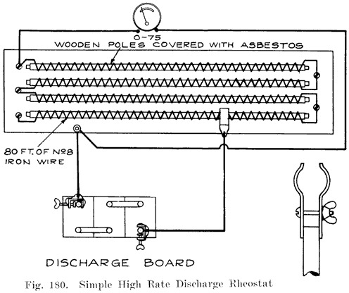
Another simple apparatus consists of a board on which are mounted six double contact automobile lamp sockets which are all connected in parallel. A pair of leads having test clips attached is brought out from the sockets for fastening to the battery terminals. Lamps of various candlepower may be turned into the sockets to obtain different currents.Discharge tests are helpful in the case of a battery that has lost capacity. The battery is first fully charged, and is then discharged at the 5 hour rate. When the voltage of the battery has fallen to 1.7 volts per cell (measured while the battery is discharging) a Cadmium test is made to determine whether the positives or negatives are causing the lack of capacity. For further descriptions of the Cadmium Test see Page 174.
In reviving sulphated batteries, it is sometimes necessary to charge and discharge the battery several times to put the active material in a healthy condition.
Discharge tests at a high rate are very valuable in diagnosing the condition of a battery. A description of such tests will be found on Page 267. For making the heavy discharge tests a rheostat of the carbon plate type is suitable. With such a rheostat currents from 25 to more than 200 may be drawn from a six volt battery, and a smooth, even variation of a current may be obtained from the minimum to the maximum values. Such a rheostat is on the market and may be purchased complete with ammeter and leads for attaching to the battery.
PACKING BATTERIES FOR SHIPPING
Batteries which are shipped without electrolyte need merely have plenty of excelsior placed around them in a strong crate for protection from mechanical injury.Batteries which are shipped filled with electrolyte must be protected from mechanical injury and must also be packed so that it is difficult to turn the crate upside down and thus allow the electrolyte to run out. A very popular crate has been the so-called "dog-house," with a gable roof such as is actually used on dog-houses. The idea of such a roof is that it is impossible to place the crate with the roof down, since it will tip over if this is done. However, if these crates are placed side by side, it is a very simple matter to put a second row of crates on top of them, turning the second row up-side-down, as shown in Fig. 181, and allowing the electrolyte to run out. The men who load freight or express-cars have often shown great skill and cunning in packing "dog-house" crates in other ways so as to damage the batteries. Many have attained a high degree of perfection in breaking the crates.
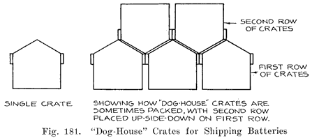
Some sort of a roof on a battery crate is required by law, the idea being to make it difficult to turn the crate up-side-down. Perhaps the best crate would be one with a flat top marked "This Side Up," but such a crate would not comply with the law.
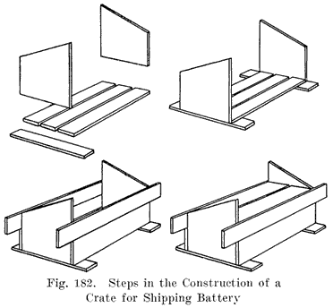
A better form of crate than the "dog-house" and one which complies with the law, is shown in Fig. 182. The top of each end piece is cut at an angle, the peak on one end being placed opposite the low point of the opposite end piece. Fig. 182 shows the steps in the construction of the crate.1. The case should be built of strong lumber (11/2 inch preferably), and of ample size to allow packing with excelsior top, bottom, sides and ends to a thickness of two or three inches. Nail strongly.
2. When the case is complete (except cover) place a thick, even layer of excelsior (or packing straw) in the bottom and set in *he battery right side up. Lay paper (preferably paraffined) over top of battery to keep it clean, then pack tightly with excelsior sides and ends.
3. Now lay sufficient packing material on top of the battery so that cover will compress it tightly, stuffing it under cover boards as they are put on.
The extended boards at bottom, and the gable roof are provided to prevent the battery from being tipped over; extensions of sides for carrying. Box should be plainly labeled: "HANDLE WITH CARE. DAMAGES CLAIMED IF TIPPED ON SIDE." In addition to the address of destination, as given in shipping instructions be sure to mark with name of shipper for identification upon arrival. When shipping by freight, the proper freight classification in the United States is "Electric Storage Batteries, Assembled." When shipping by express in the United States, "Acid" caution labels must be attached to each package.
Separators which have been given the chemical treatment necessary to remove the substances which would cause trouble in the battery, and to make the wood porous, must be kept wet and never be allowed to become dry. A lead lined box, or large earthenware jars may be used as containers. Put the separators in the container and then pour in enough very weak electrolyte to cover the separators. This electrolyte may be made of I part of 1.220 electrolyte to 10 parts of distilled water, by volume. Be very careful to have the container absolutely clean and to use chemically pure acid and distilled water in making the weak electrolyte. Remember- that impurities which are picked up by the separators will go into the battery in which the separators are placed. Therefore, keep the separator tank in a clean place and keep a cover on it. Have your hands clean when you take separators out of the tank to place in a battery, and do not put the separators on a dirty bench before inserting them between plates. The best thing to do is to hold the separators in one hand and insert them with the other, and not lay them on any bench at all.
Separators are the weakest part of a battery and wear out while the other parts of a battery are still in good condition. Good plates are often ruined by weakened separators causing short-circuits. Many batteries which have to be junked after being in service about a year would have given considerable service if they had been reinsulated.Generally the separators of one cell wear out before those of the other cells. Do not, however, reinsulate that cell alone. The separators in the other cells are as old as those which have worn out, and are very near the breaking down point. If you reinsulate only one cell, the owner will naturally assume that the other cells are in good condition. What happens? A month or so later one of the other cells "goes dead." This does not have a very soothing effect on the owner, who will begin to lose confidence in you and begin to look around for another service station.
If you explain frankly that it is useless to reinsulate only one cell of a battery and that the other cells will break down in a short time, the customer will want you to reinsulate all the cells. A somewhat higher bill for reinsulating all the cells at once will be more agreeable than having the cells break down one at a time within a month or two.
In the case of the customers who come in regularly for testing and filling service, you will be able to tell when the separators are wearing out. When you find that a battery which has been in service about a year begins to run down frequently, and suceessive tests made in connection with testing and filling service show that the generator is not able to keep the battery charged, advise the owner to have the battery reinsulated. Do not wait for the battery to have a dead cell. Sell the owner on the idea that reinsulation will prevent the possibility of his battery breaking down when he may be out on a tour, and when it may be necessary to have his car towed in to a service station. If you allow the battery to remain on the car when it begins to lose its charge, the owner will not, of course, suspect that anything is wrong, and if his battery one day breaks down suddenly, lie will very likely lose confidence both in you and the battery, since he has been bringing in his car regularly in order to have his battery kept in good shape. The sudden failure of his battery will, therefore, make him believe that you do not know your business, or that the battery is a poor one.
New separators will give every battery which is a year old a new lease on life. If you explain to a customer that he will get a much longer period of service from his battery if he has it reinsulated when the battery is a year old, you should have no trouble in getting the job, and the subsequent performance of the battery will show that you knew what you were talking about.
SAFETY FIRST FOR THE BATTERY REPAIRMAN
1. Do not work on an empty stomach-you can then absorb lead easily.2. Keep your fingers out of your mouth when at work.
3. Keep your finger nails short and clean.
4. Do not chew tobacco while at work. In handling tobacco, the lead oxides are carried to your mouth. Chewing tobacco does not prevent you from swallowing lead.
5. When you leave the shop at night, and before eating, wash your face, hands, and arms with soap, and clean your nose, mouth, and finger nails.
6. Do not eat in the repair shop.
7. Drink plenty of good milk. It prevents lead poisoning.
8. Use Epsom Salts when constipated. This is very important.
9. Bathe frequently to prevent lead poisoning.
10. Leave your working clothes in the shop.
11. It is better not to wear a beard or mustache. Keep your hair covered with a cap.
12. Before sweeping the shop dampen the floor to keep down the dust.
13. Do not drink beer or whisky, or any other alcoholic liquors. These weaken your system and make you more susceptible to lead poisoning.
14. In handling lead, wear gloves as much as possible, and -wash and dry the gloves every day that you wear them.
15. Wear goggles to keep lead and acid out of your eyes.
16. When melting lead in a hydrogen flame, as in burning on the top connectors, the fumes given off may be blown away by a stream of air. The air supply to the flame may be tapped for this purpose.
17. The symptoms of lead poisoning are: gums darken or become blue, indigestion, colic, constipation, loss of appetite, muscular pain. In the later stages there is muscular weakness and paralysis. The hands become limp and useless.
18. Wear rubber shoes or boots. Leather shoes should be painted with a hot mixture of equal parts of paraffine and beeswax.
19. Wear woolen clothes if possible. Cotton clothing should be dipped in a strong solution of baking soda and dried. Wear a flannel apron covered with sacking.
20. Keep a bottle of strong ammonia handy. If you should spill acid on your clothes, apply some of the ammonia immediately to neutralize the acid, which will otherwise burn a hole in your clothes.
21. Keep a stone, earthenware, or porcelain jar filled with a solution of washing soda or baking soda (bicarbonate of soda). Rinse your hands in this solution occasionally to prevent the acid from irritating them.
22. If you should splash acid in your eye, wash it out immediately with warm water, and drop olive oil on the eye. If you have no olive oil at hand, do not wait to get some, but use any, lubricating oil, or vaseline.
"Out of sight, out of mind," is a familiar saying. But when does it hold true?What about the battery repairman? Are the batteries he repairs "out of sight, out of mind?" Does his responsibility end when he has installed a battery on a car? Suppose he put-, a battery in first class shape, installs it on a car, and, after a week or two the battery comes back, absolutely dead? Is the battery' at fault, or is the repairman to blame for neglecting to make sure that the battery would be given a reasonably good chance to give good service and receive fair treatment from the other part of the electrical system?
The actual work on the battery is finished when the battery cables are fastened to the battery terminals. But real battery SERVICE does not end there. The battery is the most important part of the, electrical system of a car, but it is only one part, and a good battery cannot be expected to give satisfactory service when it is connected to the other parts of the electrical system without making sure that these parts are working properly, any more than a man wearing new, shoes can step into a mud puddle and not have his shoes covered with dirt.
The battery functions by means of the current which flows through it by way of the cables which are connected to its terminals. A battery is human in many respects. It must have both food and exercise and there must be a proper balance between the food and the exercise. Too much food for the amount of exercise, or too much exercise for the amount of food consumed will both lead to a lowering of efficiency, and disease frequently results. A battery exercises when it turns over the starting motor, furnishes energy to the lamps, or operates the a ignition system. It receives food when it is charged. Proper attention to the electrical system will result in a correct balance between food and exercise, or in other words, charge and discharge.
The electrical equipment of a car consists of five principal parts:
1. The Battery.2. The Ignition System.
3. The Starting Motor.
4. The Generator.
5. The Lighting System.
The normal course of operation of this system is as follows:
Starting. The ignition switch is closed, and connects the ignition system to the battery. The starting switch is then closed, connecting the starting motor to the battery. The battery sends a heavy current through the starting motor, causing the motor to turn over, or "crank" the engine. The motion of the engine pistons draws a mixture of air and gasoline vapor into the cylinders. At the proper instant sparks are made to jump between the points of the spark plugs, igniting the air and gasoline vapor mixture, forming a large amount of gas. This gas expands, and in doing so puts the engine into motion. The engine begins to run under its own power and the starting switch is opened, since the starting motor has performed the work required of it, and has nothing further to do as long as the engine runs.
The engine now operates the generator. The generator begins to build up a voltage as the engine speed increases. When the voltage of the generator has risen to about 7-7.5, the generator is automatically connected to the battery by the cutout (also known as reverse- current relay, cut-out relay, or relay). The voltage of the generator being higher than that of the battery, the generator sends a current through the battery, which "charges" the battery. As long As the engine continues to run above the speed at which the generator develops a voltage higher than that of the battery, a charging current will normally flow through. the battery. When the ignition switch is opened the engine can no longer develop any power and consequently stops running. When the decreasing engine speed causes the generator speed to drop to a point at which the generator voltage is less than that of battery, the battery sends a reverse, or discharge current through the cutout and generator, thereby causing the cutout to open and disconnect the generator from the battery.
Lights. When the engine is not running, the battery furnishes current to the lights. This is a discharge current. When the engine runs at a speed which is greater than that at which the the cutout closes, the generator furnishes current for the lights, and also for the ignition system, in addition to sending a charging current through the battery.
From the foregoing description. we see that the battery is at rest, is discharging, or charging under the following conditions:
Engine Not Running, Lamps Off, Ignition Off. Under these conditions all switches are open, and hence no current should be passing through the battery. If a current is found to be passing through the battery under these conditions, it is a discharge current which is not doing any work and is caused by a defective cutout, defective switches, or grounds and short-circuits in the wires, cables, or apparatus connected to the battery.
Starting the Engine. A heavy discharge current is drawn from the battery. This current should not flow more than 10 seconds. If the starting motor does not crank the engine or cranks it too slowly, the motor or the cables and switch connecting the motor to the battery are defective, assuming that the battery is large enough and is in a good condition. If the starting motor cranks the engine, but the engine does not begin to run under its own power within ten seconds, the starting system is not at fault, and the starting switch should be opened.
Engine Not Running, All Lamps On. A discharge current flows from the battery which is equal to the sum of the currents drawn by lamps when connected to the battery separately. If the current is greater than this sum, trouble is present.
Engine Running, Lamps Off. The generator sends a charging current into the battery and also supplies current to the ignition system (except when a magneto is used). If the generator does not send a charging current through the battery there is trouble in the generator, or in the parts connecting the generator to the battery (assuming the battery to be in a good condition). If the generator sends a current through the battery, it may be of the correct value, it may be insufficient, or it may be excessive. A normal current is one which keeps the battery fully charged, but does not overheat it or cause excessive gassing. An insufficient current is one which fails to keep the battery charged. An excessive charging current is one which keeps the battery charged, but which at the same time overheats the battery and causes excessive gassing. The excessive current may also overheat the generator, while a normal or insufficient charging current will not injure the generator.
It is possible, but not probable, that the generator may be sending &-current through the battery in the wrong direction, so as to discharge it instead of charging it. This will happen if a very badly discharged battery is installed with the connections reversed. If a fully or even partly charged battery is installed with its connections reversed, the battery will generally reverse the polarity of the generator automatically, and the battery will be charged in the proper direction, although the current flow in the charging circuit is actually reversed.
Engine Running, Lamps On. Under these conditions, the generator should supply the current for the lights, and still send a charging current of 3 to 5 amperes through the battery. This means that the current drawn from the battery when the engine is not running and the lights are all turned on should be at least several amperes less than the charging current which the generator sends into the battery when the engine is running and the lamps are turned off.
Tests to Be Made by the Repairman
The battery repairman can, and always should, make a few simple tests which will tell him whether the various conditions of operation are normal. This should be done as follows:1. Install the battery carefully (see page 236), and connect the negative battery cable to the negative battery terminal. Now tap the positive battery cable on the positive battery terminal. If a snappy spark is obtained when this is done, some of the switches are open or are defective, the cutout is stuck in the closed position, or there are grounds or short-circuits in the parts which are permanently connected to the battery.
Even though no spark is obtained when you tap the positive battery cable on the positive battery terminal, there may be some trouble which draws enough current from the battery to cause it to run down in a short time. To detect such trouble, connect a voltmeter (which has sufficient range to indicate the battery voltage) between the positive battery cable and the positive battery terminal. (Cable is disconnected from the terminal.) If the voltmeter now gives a reading equal to the voltage of the battery, there is some condition causing a current leakage from the battery, such as a cutout stuck in the closed position, defective switches which do not break the circuits when in the open position, or grounds or short-circuits in the cables and wires connected to the battery.
If the voltmeter pointer does not move from the "0" line on the scale, complete the battery connections by fastening the positive battery cable to the positive battery terminal, and make the test described in Section 2. If the voltmeter pointer moves from the "0" line, and gives a reading equal to the battery voltage, connect the voltmeter permanently between the positive battery cable and the positive battery terminal and make a general inspection of the wiring, looking for cut or torn insulation which allows a wire or cable to come in contact with the frame of the car, or with some other wire or cable, thereby causing a ground or short-circuit. Old, oil-soaked insulation on wires and cables will often cause such trouble. If a general inspection does not reveal the cause of the current leakage, proceed as follows:
Closed Cutout, or Defective Cutout Windings. (a) If the cutout is mounted outside the generator, remove the cover from it and see if the points are stuck together. If they are, separate them and see if the voltmeter pointer returns to the "0" line. If it does, you have found the trouble. The points should be made smooth with 00 sandpaper. See that the moving arm of the cutout moves freely and that the spring which tends to hold the arm in the open position is not weak or broken.
If the voltmeter pointer does not return to the "0" line when the cutout points are separated, or if the points were not found to be stuck together, disconnect from the cutout the wire which goes to the ammeter or battery. If this causes the voltmeter pointer to return to the "0" line, the cutout is defective and a new one should be installed, unless the trouble can be found by inspection and repaired.
If the voltmeter pointer does not return to the "0" line when the battery or ammeter wire is disconnected from the cutout, see paragraph (d)
(b) If the cutout is mounted inside the generator, disconnect from the generator the wire which goes to the ammeter or indicator. If this causes the voltmeter pointer to return to the "0" line, the cutout points are stuck together or the cutout is defective, and the generator should be taken apart for inspection. If this does not cause the voltmeter pointer to return to the "0" line, replace the wire and see paragraph (d).
(c) If no cutout is used and connections between the generator (or motor-generator) and the battery are made by closing the ignition or starting switch, such as is the case on Delco and Dyneto motor-generators, and some Delco generators, disconnect from the generator or motorgenerator the wire that goes to the ammeter or indicator. If this causes the voltmeter pointer to return to the "0" line, the switch which connects tile generator or motor-generator to the ammeter or indicator is defective. If the voltmeter pointer does not return to the "0" line, replace the wire and consult paragraph (d).
(d) Defective Starting Switch. Disconnect from the starting switch the cable that goes to the battery. If one or more smaller wires are connected to the same terminal as the heavy cable, disconnect them also and hold their bare ends on the bare end of the heavy cable. If this causes the voltmeter pointer to return to the "0" line, the starting switch is defective. If the voltmeter pointer does not return to tile "0" line, replace the cable and wires on the starting switch terminal and proceed as follows:
Defective Switches. See that the ignition and lighting switches are in their "OFF" positions. If they are not, open them and see if the voltmeter pointer returns to the "0" line. If it does, you have found the trouble. If it does not, disconnect from the switch (or switches, if there are separate lighting and ignition switches), the feed wire which supplies current to the switch from the battery. If this causes the voltmeter pointer to return to the "0" line, the switches are defective. If the pointer does not return to the "0" line, replace the wires on the switch and consult the next paragraph.
If there are other switches which control a spot light, or special circuits, such as tonneau lamps, or accessories, such as gasoline vaporizers, electric primers, etc., make the same tests on these switches. If no trouble has been found, see paragraph (e).
(e) Grounds or Short-Circuits in Wiring. Disconnect from each terminal point in the wiring system the wires which are connected together at that point. Also remove fuses from the fuse blocks. If the voltmeter pointer returns to the "0" line when a certain wire or fuse is removed, there is a ground or short-circuit in the wire or in the circuit to which the fuse is connected.
(f) Turn on the Lights. Remove the voltmeter and complete the battery connection-,. -Note how much current is indicated on the ammeter mounted on the instrument panel of the car as the different lamps are turned on. In each case the ammeter should indicate "discharge." Should the ammeter indicate "charge" the battery connections have been reversed, or the ammeter connections are reversed. The driver will tell you whether the ammeter has been reading "charge" or "discharge" when the lamps were turned on. This is a good way to check your battery connections.
If the car has no ammeter, or has an indicator which is marked "ON" or "OFF," or "Charge" or "Discharge," an ammeter may be connected in series with the battery by disconnecting the cable from the positive battery terminal and connecting the ammeter to the cable and to the terminal, and the readings obtained from this meter.
The amperes indicated on the ammeter should be the greatest when the main headlamps are burning bright. By comparing the readings obtained when the different lighting combinations are turned on, it is sometimes possible to detect trouble in some of the lighting lines.
3. Start the Engine. Before you do this, be sure that the cables are connected directly to the battery terminals, and that no ammeter or voltmeter is connected in series with the battery, as the heavy current drawn by the starting motor would ruin the instruments very quickly. An ammeter may be left connected in series with the battery, providing that a switch is used to short-circuit the meter while starting the engine. A meter having a 500 ampere scale may be left connected in series with the battery while the engine is being started, but for the tests which are to be made a 25 ampere scale should be used.
The engine should start within ten seconds after the starting switch is closed. If more time than this is required, carburetor adjustments, position of the choke lever, etc., should be looked after. Continued cranking of the engine will run the battery down very quickly, and the chances are that the car will not be run long enough to allow the generator to recharge the battery. Make whatever adjustments are necessary to reduce the cranking time to ten seconds, or advise the owner to have them made, warning him that otherwise you will not be responsible if the battery runs down very quickly.
4. When the engine has started, set the throttle lever so that the engine runs As slowly as possible. The ammeter (either that on the instrument panel, or a special test ammeter connected in* series with the battery) will indicate several amperes discharge, this being the current taken by the ignition system.
Now speed up the engine gradually. At an engine speed corresponding to a car speed of 7 to 10 miles per hour in "highly (if there is any difficulty in estimating this speed, drive the car around the block while making this and the following tests) the ammeter pointer should move back to, or slightly past, the "0" line, showing that the cutout has closed. If the ammeter needle jumps back and forth and the cutout opens and closes rapidly, the polarity of the battery and that of the generator are not the same. This condition may be remedied by holding the cutout points closed for several seconds, or by short-circuiting the "Battery" terminal on the cutout with the "Generator" terminal on the cutout.
After a slight movement of the ammeter pointer indicates that the cutout has closed, speed up the engine gradually. When the engine speed corresponds to a car speed of 18-25 miles per hour in "high," the current indicated on the ammeter should reach its maximum value and the pointer should then stop moving, or should begin to drop back toward the "0" line as the speed is increased.
For average driving conditions, the maximum charging current should not exceed 12 to 14 amperes for a 6 volt, 11 to 13 plate battery, and 6 to 7 amperes for a 12 volt battery. (These currents should be obtained if "constant-current" generators, such as the "third brush ... .. reversed-series," or vibrating current regulators are used. The "third brush" type of generator is used on more than 99 per cent of the modern cars. Some cars use a "constant-voltage" regulated generator, such as the Bijur generator, having a voltage regulator carried in a box mounted on the generator. On all cars using a "constant-voltage" generator, the charging rate when the battery is fully charged should not exceed five amperes for a six volt generator). If the generator has a thermostat, such as is used on the Remy generators, the charging rate will be as high as 20 amperes until the generator warms up, and then the charging rate will drop to 10-12 amperes, due to the opening of the thermostat points, which inserts a resistance coil in series with the shunt field.
If the charging current reaches its maximum value at 18-25 miles per hour, and shows no increase at higher speeds, decrease the engine speed. When the engine is running at a speed corresponding to a car speed of about 7 miles per hour, or less, the cutout should open, indicated by the ammeter indicating several amperes discharge, in addition to the ignition current, for an instant, and then dropping back to the amount taken by the ignition system.
Now turn on the headlights (and whatever lamps are turned on at the same time) and speed the engine up again. The ammeter should indicate some charging current at engine speeds corresponding to the usual speed at which the car is driven. If it does not, the charging current should be increased or smaller lamps must be installed.
The operation of the electrical system when the engine is running may not be as described in the foregoing paragraphs. Troubles may be found as follows:1. Cutout does not close until engine reaches a speed in excess of 10 miles per hour. This trouble may be due to the cutout or to the generator. If the ammeter shows a charging current of three amperes or more as soon as it closes, the cutout is at fault. The thing to do in such a case is to adjust the cutout. First see that the movable armature of the cutout moves freely and does not bind at the pivot. If no trouble is found here, the thing to do is to decrease the air gap which exists between the stationary and movable cutout points when the cutout is open., or to decrease the tension of the spring which tends to keep the points open. On most cutouts there is a stop which the cutout armature strikes when the cutout opens. By bending this stop the air-gap between the points may be decreased. This is the adjustment which should be made to have the cutout close earlier, rather than to decrease the spring tension. Some cutouts have a spiral spring attached to the cutout armature. Others have a flat spring. On still others, the spring forms the connection between the armature and the cutout frame. In the first two types, the spring tension may be decreased, but wherever possible the air-gap adjustment should be made as described.
If the cutout closes late, and only about an ampere of charging current is indicated on the ammeter, and the cutout points are fairly clean and smooth, the trouble -is generally in the generator.
The generator troubles which are most likely to exist are:
a. Dirty commutator.b. Dirty brush contact surface.
c. Loose brushes.
d. Brushes bearing on wrong point of commutator (to set brushes properly, remove all outside connections from generator, open the shunt field circuit, and apply a battery across the main brushes. Shift the brushes until the armature does not tend to rotate in either direction. This is, of course, a test which must be made with the generator on the test bench).
e. Loose connections in the shunt field circuit.
The foregoing conditions are the one-, which will generally be found. More serious troubles will generally prevent the generator from building up at all.
2. Cutout does hot open when engine stops. This condition is shown by a discharge current of about 5 amperes when the engine has stopped. (In Delco systems which have no cutout, an even greater discharge will be noted as long as the ignition switch remains closed.) This trouble is generally due to cutout points stuck together, a broken cutout spring, or a bent or binding cutout armature.
3. Cutout does not open until ammeter indicates a discharge of three or more amperes (in addition to the ignition discharge). This may be remedied by increasing the spring tension of the cutout, or removing any trouble which causes the cutout armature to bind. On many cutouts the armature does not actually touch the core of the cutout winding when the points are closed, there being a small piece of copper or other non-magnetic metal on the armature which touches the end of the cutout and maintains a small air gap between the core and armature, even when the points are closed. The opening action of the cutout may be changed by filing this piece of non-magnetic material so as to decrease the air gap, or pinching it with heavy pliers so as to make it stand farther out from the cutout armature and thus increase the air gap between the armature and core when the points are closed.
Decreasing this air gap will cause the cutout to open late, and increasing it will cause the cutout to open early.
4. Cutout will not close at any engine speed. If cutout does not close the first time the engine speed is increased, stop the engine. This condition may be due to a defective cutout, an 'open-circuit in the charging line, a ground or short-circuit between the cutout and the generator, or a defective generator. To determine whether the cutout is defective, remove the wires from it and hold together the ends of the wires coming from the generator, and the one going to the ammeter. Start the engine. If no other trouble exists, the ammeter will indicate a charging current at speeds above 8-10 miles per hour. If no current is obtained, stop the engine. If the cutout trouble consisted of an open circuit in one of its windings, or in the points not closing, due to dirt or a binding armature, or if there is an open-circuit in the charging line, the generator will, of course, have been running on open-circuit. This will cause the fuse in the shunt field circuit to blow if there is such a fuse, and if there is no such fuse, the shunt field coils may be burned open, or the insulation on the field coil wires may have become overheated to a point at which it burns and carbonizes, and causes a short-circuit between wires. Such troubles will, of course, prevent a generator from building up when the cutout wires are disconnected and their ends held together.
If there is a ground in the cutout, or between the cutout and the generator, the generator will very likely be unable to generate (if a "one-wire" system is used on the car). If there is some defect in the generator-such as dirty commutator, high mica, brushes not touching, commutator dirty, or loose brushes, brushes too far from neutral, grounded brushes, brushes not well ground in, wrong type of brushes, grounded commutator or armature windings, short-circuited commutator or armature windings, open-circuited armature windings, grounded field windings, short-circuited field windings, open-circuit or poor connections in field circuit, one or more field coil connections reversed, wrong type of armature or field coils used in repairing generator, generator drive mechanism broken-then the generator will not build up.
If no charging current is, therefore, obtained when the generator and ammeter wires are disconnected from the cutout and their ends held together, there may be a ground or short-circuit in the cutout windings or in the circuit between the generator and the cutout, or the generator may be defective, due to having been operated on open-circuit, or due to troubles as described in the foregoing paragraph. The presence of a ground or short in the circuit between the generator and cutout or in the cutout may be determined by disconnected the wire from the generator, disconnecting the battery (or ammeter) wire from the cutout, and running a separate extra wire from the generator to the wire removed from the cutout. Then start the engine again. If a charging current is obtained, there is a ground or short either in the cutout or in the circuit between the cutout and the generator. (It is also possible that the failure of the generator to build up was due to poor brush contact in the generator. The use of the extra wire connected the generator directly to the battery, thus magnetizing the generator fields and causing generator to build up. If poor brush contact prevented the generator from building up, closing the cutout by hand will often cause the generator to start charging. If you can therefore cause the generator to build up by holding the cutout points closed by hand, or by shorting across from the generator terminal to the battery terminal of the cutout, it is probable that the generator brushes are not making good contact). The cutout may be tested by stopping the engine, replacing the battery (or ammeter) wire on the cutout, and holding the end of the extra wire on the generator terminal of the cutout. If a charging current is then obtained, the cutout is 0. K. and the trouble is between the cutout and the generator.
5. An excessive current is obtained. If a third brush generator is used, look for loose or dirty connections in the charging line, dirty cutout points, dirty commutator, dirty brushes (especially the brush, or brushes, which is Dot connected to one end of the field winding), brushes loose, brushes not well ground in, and any other conditions which will cause a high resistance in the charging line. It is characteristic of third brush generators that their current output increases if there is an increase in resistance in the charging circuit. If no troubles such as those enumerated above are found, the third brush may need adjusting.
Generators using vibrating current or voltage regulators will give an excessive output if the points need adjusting or if the regulating resistance is short-circuited.
Generators using reversed series regulation will give an excessive output if there is a short-circuit in the series field coils.
6. Low charging current is obtained. This may be due to adjustment of the regulating device, to high resistance in the shunt field circuit in case of a third brush generator. In case of generators using other kinds of regulation, loose connections, dirty commutator and brushes, etc., will cause low charging current.
7. Generator charges up to a certain speed and then stops charging. The trouble is caused by some condition which causes the brushes to break contact with the commutator, especially in the case of a "third" brush. High mica, loose brush spring, or a commutator which has been turned down off-center may cause the trouble. This trouble most frequently occurs on cars using third brush motor-generators having a 3 to 1 or more speed ratio between them and the engine. These motor-generators operate at such high speeds that high mica and a commutator which is even slightly off center have a much greater effect than the same conditions would cause in separate generators which operate at much lower speeds. The remedy for this trouble is to keep the mica under-cut, and to be very careful to center the armature in the lathe when taking a cut from the armature. In turning down the commutators of high speed motor-generators, special fittings should be made by means of which the armature may be mounted in its own ball-bearings while the commutator is turned down.
The repairman should be very slow in adjusting generator outputs. Most cases of insufficient or excessive charging current are due to the troubles enumerated in the foregoing paragraphs, and not due to incorrect adjustment of the regulating device. Before changing the adjustment of any generator, therefore, be sure that everything is in good condition. The third brush generator, for instance, will have an excessive output if the brushes are dirty, loose, or not well seated on the commutator. The use of a third brush which is too wide, for instance, will change the output considerably. A high resistance third brush will decrease the output, while a low resistance brush will increase the output. On the other hand, an increase in the resistance of the charging circuit will cause an increase in the output of a third brush generator, which is just the opposite to what is ordinarily expected. Such an increase in resistance may be due to loose or dirty connections, dirty cutout contact points, corroded battery terminals and so on. Remember also that the third brush' generator sends a higher current into a fully charged battery than it sends into a discharged battery. It is, therefore, essential that a fully charged battery be on the car when the output of a third brush generator is adjusted.There are two things which determine whether any change should be made in the charging rate on the car, viz: Driving, Conditions and the Season of the Year.
Driving Conditions. A car which makes short runs, with numerous stops, requires that the starting motor be used frequently. This tends to run the battery down very quickly. Moreover, such a car usually does not have its engine running long enough to give the generator an opportunity to keep the battery charged, and to accomplish this, the charging rate should be increased.
A car which is used mostly at night may need a higher charging rate, especially if short runs are made, and if the car stands at the curb with its lights burning. Long night runs will generally call for only a normal charging rate, since the long charging periods are offset by the continuous use of the lamps.
A car used on long daylight runs should generally have the charging rate reduced, because the battery is charged throughout such runs with no discharge into lamps or starting of motor to offset the continued charge. If the lamps are kept lighted during such runs, the normal charge rate will be satisfactory, because the lamp current will automatically reduce the current sent into the battery.
In the winter time, engines must be cranked for a longer time before they will start, the battery is less efficient than in warm weather, and lights are burning for a greater length of time than in summer. Such conditions require an increase in the charging rate, especially if the car is used on short runs. Oil long runs in the winter time, the normal charging rate will generally be satisfactory because the long charging period will offset the longer cranking period.
In the summer time, engines start more easily than in winter, and hence require less cranking. The lamps are used for only short periods and the battery is more efficient than in winter. A lower charging rate will, therefore, keep the battery charged. Long tours in the summer time are especially likely to result in overcharged, overheated batteries, and a reduced charging rate is called for.
How and When to Adjust Charging Rates
A correct charging rate is one which keeps a battery fully charged, but does not overcharge it, and which does not cause either the generator or the battery to become overheated. The only way to determine whether a certain charging rate is correct on any particular car is to make an arrangement with the car owner to bring in his car every two weeks. On such occasions hydrometer readings should be taken and water added, if necessary, to bring the surface of the electrolyte up to the proper level. The hydrometer readings will show whether the generator is keeping the battery charged, and if a change in the charging rate is necessary, the necessary adjustments may be made. If a customer does not bring in his car every two weeks, call him up on the phone or write to him. The interest which you show in his battery by doing this will generally result in the customer giving you all his repair business, and he will also tell his acquaintances about your good service. This will give you considerable "word of mouth" advertising, which is by far the best form of advertising and which cannot be bought. It must be earned by good battery service.Adjusting a third brush generator. The best rule to remember for changing the output of a third brush machine is that to increase the output, move the third brush in the direction in which the commutator rotates, and to decrease the output, move the third brush in the opposite direction. Move the third brush only 1/16 inch and then sandpaper the brush seat with 00 sandpaper. Allow the generator to run for about twenty minutes to "run-in" the brush. Then vary the speed to see what the maximum charging rate is. If the change in the charging rate is not sufficient, move the third brush another 1/16 inch and proceed as before until the desired charging rate is obtained.
Adjusting Vibrating Regulators. The output of generators which use a vibrating regulator is adjusted by changing the tension of the spring fastened to the regulator arm. In many cases this adjustment is made by means of a screw which is turned up or down to change the spring tension. In other cases a hook or prong is bent to change the spring tension. Where a coil spring is used, lengthening the spring will decrease the tension and lower the output, while shortening the spring will increase the tension and raise the output.
Vibrating regulators are of the "constant" current or the "constant-voltage" types. The constant current regulator has a winding of heavy wire which carries the charging current. When the charging current reaches the value for which the regulator is set, the electromagnet formed by the coil and the core on which it is wound draws the regulator armature toward it and thereby separates the regulator points, which are in series with the shunt field. A resistance coil, which is connected across the regulator points and which is short-circuited when the points are closed, is put in series with the shunt field when the points separate. This reduces the shunt field current, causing a decrease in generator voltage and hence current output. As the current decreases, the pull of the electromagnet on the regulator armature weakens and the spring overcomes the pull of the electromagnet and closes the regulator points. This short-circuits the resistance coil connected across the regulator points and allows the shunt field current to increase again, thereby increasing the generator output. This 'cycle is repeated at a high rate of speed, causing the regulator points to vibrate rapidly.
The action of a vibrating "constant-voltage" regulator is exactly the same as that of the "constant current" regulator, except that the coil is connected across the generator brushes. The action of this coil therefore depends on the generator voltage, the regulator points vibrating when the generator voltage rises to the value for which the regulator is set.
Adjusting Reverse-Series Generators. The regulation of the output of this type of generator is accomplished by means of a field winding which is in series with the armature, and which therefore carries the charging current. These series field coils are magnetically opposed to the shunt field coils, and an increase in charging current results in a weakening of the field flux. A balanced condition is reached at which no increase of flux takes place as the generator speed increases, the tendency of the increased shunt field current to increase the total flux being counterbalanced by the weakening action of the flux produced by the series field current.
To increase the output of a reverse series generator, it is necessary to weaken the opposing series field flux. The only way of doing this is to short-circuit the series field coils, or connect a resistance across them. To decrease the output of a reverse series generator, a resistance coil may be connected in series with the shunt field winding. Neither of these schemes is practicable, and hence the reverse series generator may be considered as a "non-adjustable" machine. Under-charging may be prevented by using the starting motor and lights as little as possible, or by giving the battery a bench charge occasionally. Over-charging may be prevented by burning the lights whenever the engine is running, or leaving the lights turned on over night.
Other forms of regulation have been used on the older cars, but the majority of the cars now in use use one of the four forms of regulation described in the foregoing paragraphs. If adjustments need to be made on some car having a system of-regulation with which the battery man is not familiar, the work should be done in a service station doing generator work.
If generator outputs are changed because of some special operating condition, such as summer tours, the rate should be changed to normal as soon as the usual driving conditions are resumed.
Every man expects to be paid for his work, since his purpose in working is to get money. Yet there are numerous instances in every line of work requiring work to be done for which no money is received. The term "Free Service" is familiar to every repairman, and it has been the cause of considerable discussion and dispute, since it is often very difficult to know where to draw the Tine between Free Service and Paid Service.The term "Free Service" might be abolished with benefit to all concerned. In the battery business "Free Inspection" service is a familiar term. It is intended to apply to the regular addition of distilled water by the repairman and to tests made at the time the water is added. Since the term "Inspection" might be Misinterpreted and taken to apply to the opening of batteries for examination, the term "Testing and Filling Service" should be used instead of "Free Inspection Service."
Battery makers furnish cards for distribution to car owners. These cards entitle the holder to bring in his battery every two weeks to have distilled water added if necessary, and to have his battery tested without paying for it. This service requires very little time, and should be given cheerfully by every service man.
"Testing and Filling Service" is an excellent means of becoming acquainted with car owners. Be as pleasant and courteous to the "Testing and Filling" customer as you are to the man who brings in a battery that needs repairs. For this customer will certainly give you his repair business if you have been pleasant in giving the Testing and Filling Service.
A thoroughly competent battery man should be put in charge of the Testing and Filling Service, since this man must meet the car owners, upon whom the service station depends for its income. Customers are impressed, not by an imposing array of repair shop equipment, but by the manner of the men who meet them. These men will increase the number of your customers, or will drive trade to competitors, depending on the impression they leave in the minds of the car owners.
Every service station owner should persuade all the car owners in the vicinity of the station to come in regularly for the free testing and filling service, and when they do come in they should be given cheerful, courteous service. Each "testing" and "filling" customer is a prospective paying customer, for it is entirely natural that a car owner will give his repair work to the battery man who has been taking care of the testing and filling work Oil his battery. When a new battery is needed, the "testing" and "filling" customer will certainly buy it from the man who has been relieving him of the work of keeping his batter.), in good shape.
Car owners who depend on your competitor for their "testing and filling" service will not come to you when their battery needs repairing, or when they need a new battery. You may be convinced that you handle a better make of battery than your competitor does, but your competitor's word will carry far more weight than yours with the man who has been coming to him for testing and filling. Good testing and filling service is, therefore, the best method of advertising and building up your business. The cost of this service to you is more than offset by the paying business it certainly brings, and by the saving in money spent for advertising. Remember that a boost by a satisfied customer is of considerably greater value to your business than newspaper advertising.
A careful record should be kept of every battery which is brought in regularly for testing and filling service. If a test shows that one or more cells are low in gravity, say about 1.220, this fact should be recorded. If the gravity is still low -when the battery comes in again for test, remove the battery and give it a bench charge. The customer should, of course, pay for the bench charge and for the rental battery which is put on the car in the meantime.
Battery manufacturers generally furnish cards to be used in connection with the testing and filling service, such cards being issued to the customers. A punch mark is made every time the battery is brought in, If the owner neglects to come in, this is indicated by the absence of a punch mark, and puts the blame for any trouble caused by this neglect on the owner. if any cell shows low gravity, a notation of that fact may be made opposite the punch mark for the date on which the low gravity was observed. If the low gravity is again found the next time the battery is brought in, the battery should be removed and given a bench charge. If the bench charge puts the battery in good shape, and the subsequent gravity readings are high, no trouble is present. If, however, the low gravity readings begin to drop off again, it is probable that new separators are required, especially if the battery is about a year old.
The logical course of events in the testing and filling service is to keep the battery properly filled (at no cost to the customer), give the battery an occasional bench charge (for which the customer pays), reinsulate the battery when it is about a year old (for which the customer pays), and sell the customer a new battery when the old one is worn out. If some trouble develops during the lifetime of the battery which is not due to lack of proper attention, the customer should pay to have the repairs made. From this the battery man will see how the Testing and Filling Service pays. The way to get business is to have people come to your shop. Become acquainted with them, treat them right, and you need not wonder where the money is to come from.
In order to run a repair shop in an orderly, business-like manner, it is necessary to have an efficient system of Service Records. Such a system will protect both the repairman and the customer, and simplify the repairman's bookkeeping. For a small service station a very simple system should be adopted. As the business grows, the service record system must necessarily become more complicated, since each battery will pass through several persons' hands. Battery manufacturers generally furnish service record sheets and cards to their service stations, and the repairman who has a contract with a manufacturer generally adopts them. The manufacturers' service record systems are often somewhat complicated, and require considerable bookkeepingFor the smaller service station a single sheet or card is most suitable, there being only one for each job, and carbon sheets and copies being unnecessary. Such a service record has three essential parts: (a) The customer's claim check. (b) The battery tag. (c) The record card. Fig. 183 shows a service record card which is suitable for the average repair shop. Part No. I is the customer's claim check, Part No. 2 the battery tag, and part No. 3 the record card, and is 5 inches by 8 inches in size. The overall size of the entire card is 5 inches by 12 inches. Parts I and 2 are torn off along the perforated lines marked (A).
When a battery comes in the three parts are given the same number to identify them when they have been torn apart. The number may be written in the "No." space shown on each part, or the numbers may be stamped on the card. The record should not be made out as soon as a customer comes in, but after the battery has been examined and tested and the necessary work determined. Put the customer's name on parts 2 and 3. Record the address, telephone, etc., in the proper spaces on part 3. Having determined by test and inspection what is to be done, fill out the "WORKCOSTS" table on part 3, putting a check mark in the first column to indicate the work to be done and the material needed. Figure up the cost while the customer waits, if this is possible. Explain the costs to the customer, and have him sign Contract No. 1. If you do this there can never be any argument about the bill you hand the customer later If the customer cannot wait, or if he is well known to you and you know lie will not question your bill, have him sign Contract No. 2. In either case, the terms printed on the back of the card authorize the repairman to make whatever repairs he finds to be necessary, and bind the customer to pay for them. Find out whether the customer will call, whether you are to deliver the battery, or whether you are to ship it, and put a check mark in the proper space at the right of the "WORK-COSTS" table. Mark the battery with the chalk whose color is indicated, and you will know how to dispose of the battery when the repairs are completed.
Fill out the claim check and give it to the customer, tearing it off along the perforated lines. Fill out the battery tag, indicating after "Instructions" just what is to be done. Make a sketch of the top of the battery in the space provided, dip the tag in the paraffine dip pot (see page 182) and tack the card on the battery. File part 3 in a standard 5 by 8 card index file. To the right of the "WORK-COSTS" table are spaces for entering the date on which the work is completed, the date the customer is notified and the date the battery goes out. These dates are useful in keeping a record of the job. When the job is finished and the rental comes in, enter the costs in the "COSTS" table, and note the date the bill was paid, in the space marked "PAID."
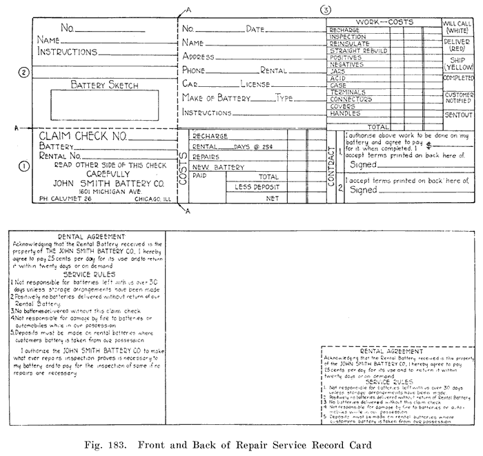
File all the 5 by 8 cards (Part 3) in alphabetical order in a "dead" ticket file, in either alphabetical or numerical order. With this file you can build up an excellent mailing list of your customers. You can note how many new customers you are securing and how many customers are not coming back. The latter information is very valuable, as it enables you to find out what customers have quit, and you can go after them to get their repair business again.
When a rental is put on a card, the card shown in Fig. 184 may be tied to the car where it is easily seen. This will serve as a reminder to the customer and will help advertise your shop to those who ride in the car. |
|
The Record Card shown in Fig. 183 does not help you locate any particular rental battery. For instance, suppose that rental battery No. 896 is out and you wish to know who is using it. You may, of course, look over the "Battery Tags" which are tied to the batteries which are being repaired in the shop, or you may examine the file containing the record cards, but this would take too much time. But if you refer to the rental file you can determine immediately where rental battery No. 896 is, since the cards in this' file should be arranged numerically.The rack on which rental batteries are placed should have a tag bearing the same number as the rental battery tacked to the shelf below the place provided for the battery. Each rental battery should always be placed in the same place on the shelf. You can then tell at a glance which batteries are out.
A good plan, and one which will save space, is to write the number of the rental battery on the customer's claim check, and when repairs on his own battery are completed, to set his battery in the place provided on the rental rack for the rental which he is using. When he comes in for his battery, you can tell at a glance whether his battery is ready by looking at the place where the rental he is using is normally placed on the rental rack. If a battery is there you will know that it is his battery, and that it is ready for him.
(Omitted Fig. 185 showing "Rental Battery Stock Card" which simply showed date out, date in, days out and customer's name, address and phone. The following Chapter 13 - Business Methods which contained Figs. 186, 187 and 188 was omitted.).
You could, of course, look through the batteries on the "Ready Rack," but this would take more time, since the numbers of the batteries on this rack will always be different, and you would have to look through all the batteries on the "Ready Rack" before you would be able to tell whether any particular battery were ready. By putting a customer's battery in place of the rental he is using, you will have only one place to look at in order to know whether his battery is ready.
|
|
|
| |||||||||