CHAPTER 16
SPECIAL INSTRUCTIONS
EXIDE BATTERIES
Exide batteries may be classified according to their cover constructions as follows:1. Batteries with single flange covers, as shown in Figs. 15 and 238. This class includes types DX, LX, LXR, LXRV, PHC, XC, XX, and XXV.
2. Batteries with double flange covers, as shown in Fig. 242. This class includes types MHA, KZ, KXD, LXRE, and XE. The cover constructions are-described in Chapter 3.All Exide batteries, except types KXD, LXRE, and XE, have burned-in lead top connectors. All types have a removable sealing nut around each post to make a tight joint between the post and cell cover, as described on page 19. Formerly some Exide batteries had cell connectors -which were bolted to the cell posts, but this construction is now obsolete. Types KXD, LXRE, and XE have cell connectors made of flexible, lead coated copper strips.
Types DX, LX, LXR, LXRV, MHA, PHC, XC, XX, and XXV have been designed and built to meet the requirements of starting, lighting and ignition service* for passenger automobiles and power boats.
Types KXD, LXRE, and XE have been especially developed to meet the requirements of the starting, lighting and ignition service on motor trucks and tractors.
Type KZ has been produced particularly for motorcycle lighting and ignition service.
The type of an Exide battery is stamped on the battery name plate. Thus, on one of the most popular Exide batteries is marked Type 3-XC-13-1. Other Exide batteries have different numerals and letters in their type numbers, but the numerals., and letters are always arranged in the same order as given above. The first numeral gives the number of cells. The letters give the type of cell. The numerals following the letters give the number of plates per cell. The last numeral indicates the manner of arranging the cells in the battery case. Thus, in the example given above, 3-XC-13-1 indicates that there are three cells in the battery, that the type of cell is XC, that each cell has 13 plates, and that the cells are arranged according to method No. 1, this being a side to side assembly.
Methods of Holding Jars in Case
Two methods of holding Exide jars in the battery case are used:1. Types MHA, KXD, LXRE, and XE have the jars separated by horizontal wooden spacers, there being two spacers between adjoining jars. Running horizontally between these two spacers are tie bolts which pass through the case. These bolts are tightened after the jars are placed in the case, thus pressing the sides of the case against the jars and holding them in, place.
Types KXD, LXRE, and XE, in addition to the tie bolts, are secured in the case by sealing compound beneath and around the jars. Each cell is provided with two soft rubber buffers which are V shaped, and are placed over the ridges in the bottom of the jars, thereby minimizing the effect of shocks on the plates and separators which rest on the buffers.
2. In types DX, LX, LXR, LXRV, PHC, XC, XX, and XXV, there are no spacers between adjoining jars, and the jars simply fit tight in the case. Should they not fit tight enough to hold them in place securely, thin boards are inserted between the jars and the case to pack them in.
Type KZ has the three sets of plates in one jar, having three compartments, with a three compartment cover.
1. Drilling Off the Top Connectors. Do this as described on page 329. For type KZ batteries use a 3/8 inch drill. For all other types use a 5/8 inch drill.2. Removing Plates from Jars. Follow the general instructions on page 333.
Types DX, LX, LXR, LXRV, PHC, XC, XX, and XXV. In opening these batteries, all of which have the single flange cover, you may remove each cell complete from the case, and then draw out the plates; or you may draw out the plates without taking out the jars. To remove the complete cell, heat a thin bladed putty knife and work it down all around the outside of the jar. Then lift out the complete cell by pulling steadily on the cell posts with two pairs of gas pliers. The battery should be placed on the floor when you do this, and you should stand with one foot pressed against the side of the case.
If you do not wish to remove the complete cells, or should the jars fit too tight in the case, unseal the covers and remove the plates according to the instructions given on page 333.
Types KZ and MHA. These batteries have the double flanged cover. Several methods may be used in removing the plates from the jars. In each case, the top of the cell is cleaned, gas blown out of the vent holes, and the sealing nuts removed before opening the cells.
|
|
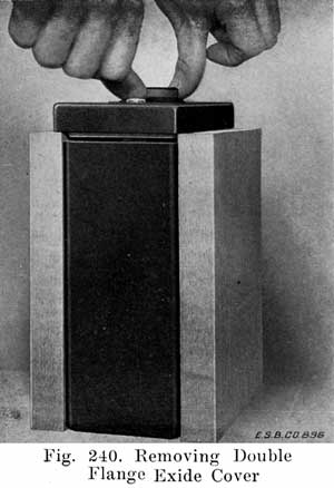
First, a flame may be used to soften the sealing compound which is placed in the slot formed by the two flanges of the cover. If you wish to use a flame, first remove each complete cell from the case, loosening the tie bolts that pass through the case to release the jars. Then hit out each complete cell. Now get two strong boards which are about one fourth inch longer than the height of the jar. See Fig. 240. Support the jar on these boards by resting the lower edge of the sides of the cover on the top edge of the boards. Then run a moderate flame around the outside of the flange until the cover is soft, and the compound melting. Then press down on the cell posts with your thumbs, and the jar. and plates will drop free of the cover. The plates are then drawn out and rested on the top of the jars to drain, as usual. |
Work on Plates, Separators, Jars, and Case
Having opened the battery, follow the instructions given on pages 335 to 361 for examination of plates and separators, and all work on plates, jars, separators, and case.
|
|
First slip the positive and negative groups together without separators. Then wipe the posts with a rag moistened with ammonia, rinse them with water, and dry thoroughly with a clean rag. Next slip the soft rubber washers over the posts and place the cover in position. Lubricate the lead sealing nuts with graphite that has been mixed to a paste with water. Do not use grease or vaseline to lubricate these nuts. Then put on the sealing nuts and tighten them partly with your fingers. |
Putting Plates In Jars
The next step is to lower the plates into the jars, as described on page 362. In types KXD, LXRE, and XE be sure to first replace the two soft rubber buffers in the bottom of the jar, one over each ridge.
Filling Jars With Electrolyte
As soon as you have an element in place in the jar, fill the jar with electrolyte of the proper strength, as described on page 364, to prevent the separators and plates from drying. The negatives, especially, must be covered with electrolyte to prevent them from heating and drying.
For Types DX, LX, LXR, LXRV, PHC, XC, XX, and XXV, which have the single flange type of cover, slowly heat the sealing compound until it runs, but do not get it so thin that it will run down into the cell between the cover and jar. Then pour it into the channel between cover and jar walls. Allow it to cool and finish it off -flush with a hot knife. When pouring, be sure the compound is liquid and not lumpy, as in such a case a poor seal will result. A glossy, finished appearance may be given to the compound by passing a flame over it after the job is finished.
|
|
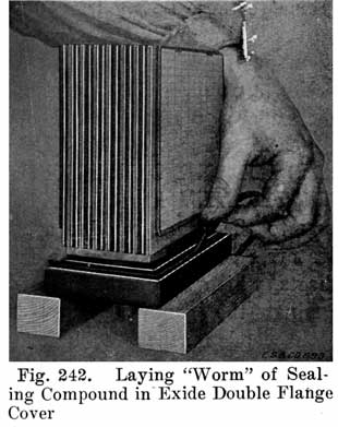
For Types KXD, KZ, LXRE, MHA, and XE, which have the double flange type of cover, have ready a string or worm of sealing compound about 3-16 inch in diameter, made by rolling between boards some of the special compound furnished for the purpose. The cover may or may not have been attached to the element, depending on how repairs have been made. In either case the procedure is the same as far as sealing is concerned. Assuming the element is attached, stand it upside down, with the cover resting upon two strips, Fig. 242. Lay the string of compound all around the cover channel. Now turn right side up and insert in the jar, taking care that the jar walls enter the cover channels at all points. Apply heat carefully to the edges of the cover and gently force cover clown. If too much compound has been used, so that it squeezes out around the cover, scrape off the excess with a hot knife while forcing cover down. |
(Chart "Capacity of Exide Batteries" Omitted. Information not really useful.)
When the covers have all been sealed, put the cells in the case, taking care to put the negative and positive posts in their proper positions, so that each cell connector will connect a positive to a negative post.In Types MHA, KXD, LXRE, and XE, which have wooden spacers between the cells, take care that the spacers- are in position and then, after cells are in place, tighten the tie bolts with a screw driver to clamp the jars.
In Types DX, LX, LXR, LXRV, SX, XC, XX, and XXV the cells should fit tight in the case; pack them in with thin boards if necessary.
Burning on the Cell Connectors
See instructions on pages 213 to 216.
See also instructions on page 373.Not sooner than ten to fifteen hours after filling battery with electrolyte, add electrolyte to restore level if it has fallen.
The instructions for rebuilding batteries which have already been given, pages 328 to 374, apply also to all U. S. L. batteries. In working on the old U. S. L. batteries, illustrated in Fig. 243, draw out the electrolyte down to the tops of the plates so that the electrolyte is below the lower end of the vent tube. Then blow out any gas which may have collected under the cover with compressed air or bellows. Never fail to do this, as there is only a small vent hole in the cover through which the gas can escape, the vent tubes extending down into the electrolyte when the cells are properly filled.
Fig. 244 shows the new U. S. L. cover construction. Note that the special cell filling device is no longer used. U. S. L. batteries have lead bushings moulded into the cover. These bushings fit around the posts, and are burned to the posts and top connectors, Figs. 243 and 244, thus giving leak proof joints between the cover and the posts. In burning on the connectors, melt bottom edge of hole first, then top of post and cover bushing, and melt in your burning lead slowly.
(Two charts - "Capacity of U.S.L. Batteries" omitted. Information not really useful.)
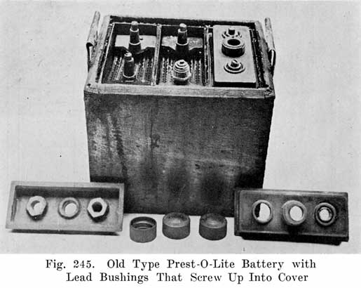
Some of the old Prest-O-Lite batteries have a lead bushing around the post, Fig. 245, similar to the U. S. L. batteries. This will make a perfectly tight seal, provided that you screw the. bushing up tight. The new types of Prest-O-Lite batteries have a "Peened" post seal, special instructions for which follow.The general instructions for rebuilding batteries given on pages 328 to 374 apply to Prest-O-Lite batteries in every respect. The "Peened" post seal is, however, a special construction, and directions for working on this seal are as follows:
|
|
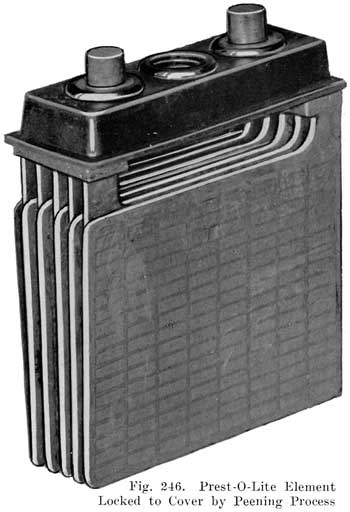
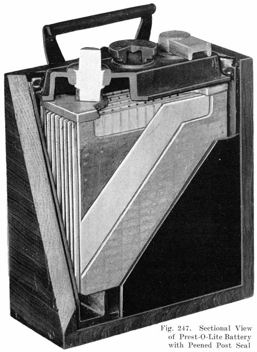
All Prest-O-Lite batteries designated as Types WHN, RIJN, BHN, JFN, KPN, and SHC, have a single moulded. cover which is locked directly on to the posts of the element. This feature is the result of forcing a solid ring of lead from a portion of the post, projecting above the cover, down into a deep chamfer in the top of the cover. Figs. 246 and 247 show this construction. |
However, where the cover is broken or must be replaced for other reasons, when plates have to be renewed, or the posts have been broken off below the cover, the element and cover must be separated.All the apparatus and special tools which are used in connection with the locking, as well as the building-up, unlocking (freeing), and rebuilding, of the posts in all Prest-O-Lite battery types are grouped together and collectively termed the type "N" Post Locking Outfit.
This outfit, complete, is carried in stock at all Prest-O-Lite warehouses under the part number 27116. Each of the individual parts or tools also has a separate part number and may be bought separately.
Prest-O-Lite Type "N" Post Locking Outfit
|
Arbor Press (complete with following 12 parts) |
27115 |
|
Main Casting |
27114 |
|
Latch |
27107 |
|
Bed Plate |
27113 |
|
Lever |
27108 |
|
Rack |
`27211 |
|
Washer |
27112 |
|
Pinion Shaft |
27110 |
|
Pinion |
27109 |
|
Latch Pin |
27111 |
|
*Special CLN & KPN Spacer |
27233 |
|
*Special CLN & KPN Latch |
27232 |
|
*Special CLN & KPN Bed Plate |
27234 |
|
Large Peening Tool (9-21 RHN, WHN, BHN, SHC, KPN, CLN; 11-17 JFN) |
27101 |
|
Small Peening Tool (7-WHN, RHN, SHC; 9-JFN) |
27100 |
|
Peening Tool for small terminal posts in which are east threaded brass inserts (Columbia) |
27105 |
|
Large Post Freeing Tool |
27103 |
|
Small Post Freeing Tool |
27102 |
|
No. 8 Post Freeing Tool (13/16" diameter straight post) |
27123 |
|
1 Large Post Re-Builder (9-21 RHN, WHN, BHN, SHC, KPN, CLN; 11-17 JFN) |
27005 |
|
1 Small Post Re-Builder (7-WHN, RHN, SHC; 9-JFN) |
27004 |
|
2 Ford Positive Post Builder |
27006 |
|
2 Ford Negative Post Builder |
27224 |
|
2 No. 8 Post Builder (13/16" diameter straight post) |
27225 |
|
Style "B" Prest-O-Lite Torch, with six feet of red gum tubing |
A-3116 |
|
Automatic Reducing Valve |
A-427 |
|
COMPLETE TYPE "N" OUTFIT including all parts above |
27116 |
* The CLN and KPN Spacer block, bent Latch and Bed Plate are special parts used only in the Arbor Press when it is especially assembled to lock CLN or KPN posts.1 The Re-Builder is used to build up posts before attempting to lock on the cover. The replacing of the metal cut away from the original diameter of the post when the jar cover was removed is necessary to the correct operation of the Peening Tool.
2 The Builder is used to build up posts, after they have been locked and shaped by the Peening Tool, to a size large enough to take some special terminal. For example, the Ford Positive Post Builder is used in building up posts, locked by the Large Peening Tool, to the proper size to take the Ford positive terminal.
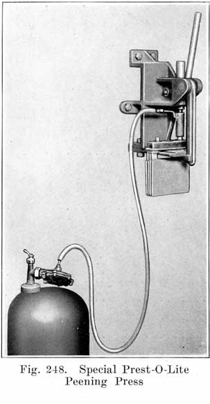
The Automatic Reducing Valve delivers the gas from the P-O-L tank at a uniform pressure of 3 pounds per square inch, whether the tank is full, half empty, or nearly empty, and regardless of the volume of gas used. The volume or flow of gas is regulated by the key.
The style "B" torch mixes the pure acetylene from the gas tank with the proper amount of air necessary to an efficient heating flame.
The heating flame is conducted or delivered to the Peening Tool by the short length of brass tubing known as the Torch-Holder, over which the "B" Torch is pressed by hand in completing the assembly.
|
|
Both the "B" Torch and the Automatic Reducing Valve are absolutely essential to the use of the Prest-O-Lite gas tank for heating the Peening Tool. |
In using the Press to lock CLN or KPN posts it is necessary to remove the Bed Plate and the Latch, and replace these parts with the Special Bed Plate and Special Latch provided for this purpose, using the spacing block or Spacer (also provided) between the Special Bed Plate and the bottom of the Press.
|
|
|
To Remove Cell Covers from Elements
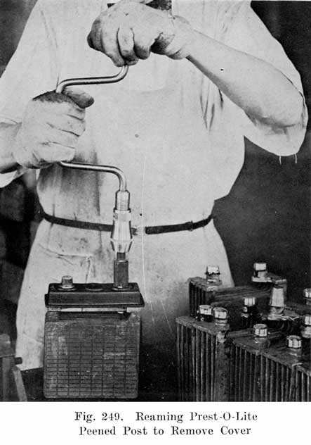
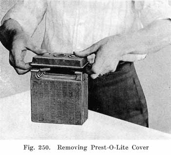
Drill off cell connectors and terminals as usual. Insert the proper size Freeing Tool (or reamer), furnished with the outfit, in an ordinary hand-power drill press or bit-and-brace. With this reamer remove the ring of metal or flange on the post, thereby releasing the cell cover. Fig. 249. The Freeing Tool should not be used in a power-driven press, as slow speed is essential to prevent breaking cell covers. To get the best results, center the Freeing Tool over the post, gradually forcing it down, at the same time keep it turning slowly until the ring of metal which locks the post in the cover has been removed. A little machine oil should be put on the metal directly under the tool for this operation. After the metal ring has been removed, the cover can be easily lifted off the posts, Fig. 250.
![]()
The use of the Freeing Tool in removing the cell cover cuts away a certain amount of metal from the diameter of the posts. Before these posts can be relocked by the Peening Tool in replacing the cell cover they must be built up in size or diameter again so that there will be enough lead to insure a tight joint.
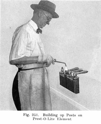
Thoroughly clean the post. Place the proper Post Re-Builder so that it rests on the shoulder of the post, and run in enough new lead to fill the Re-Builder. Fig. 251. Be sure and bring the lead surface of the post into fusion before the new lead is run in, to insure a strong post.To build a smooth, solid post, be sure that the post is thoroughly clean; then use a hot flame.
(1) Assemble positive and negative groups without separators, and paint the posts (just above the shoulder) with hot sealing compound.(2) Prepare the cell covers by immersing them in hot water until they are flexible.
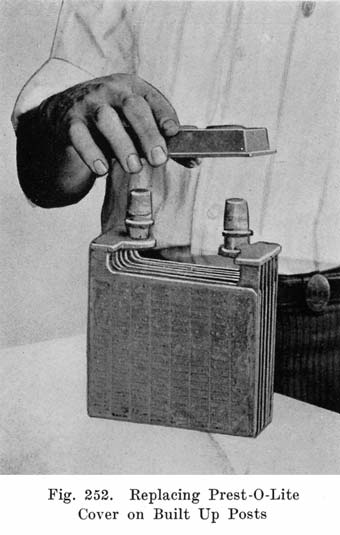
(3) Place a warmed cover over the posts of the two assembled groups (the elements). Fig. 252.
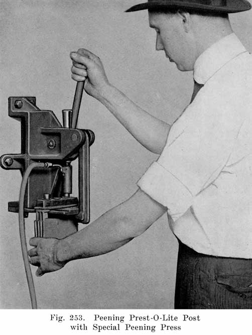
(4) Slide the element over the Bed Plate directly under Peening Tool, with the bottom of the plate connectors resting on the Bed Plate. (See Fig. 253).(5) Pull down the Latch to hold the Bed Plate in alignment.
(6) Center the post with Peening Tool. Then force the Peening Tool down slowly until it has covered about two-thirds of the distance to the cover. Pause in this operation to allow the metal of the post to become heated; then force tool the rest of the distance. Raise the Peening Tool slightly and force down again.
(7) Release the Latch, withdraw and reverse the element, and repeat operations 4, 5 and 6 on the other post.
(8) The assembled groups are now ready to receive separators.
Precautions in Post Locking Operations
1-Be sure all covers are warmed until they are flexible before attempting to assemble.2-Be sure that the Peening Tool is not too hot. If it is, the post will melt away and be ruined. A very hot tool sometimes causes dangerous spattering of hot lead.
3-Be sure that the post is centered with the Peening Tool before forcing the Tool down on the post.
4-Be sure the cover has been forced down, so that it rests on the shoulder of the post, before releasing.
In breaking in a new Peening Tool it is advisable to squirt several drops of machine oil inside the Tool, as well as putting some oil on the top of the post, before forcing the hot Tool down over the post. This will prevent the Tool from sticking to the post.If the Peening Tool should stick to the post, force the Tool down again, being certain that the cover is slightly compressed. Sticking of the Peening Tool indicates either that the Tool has not yet been broken in, or that there is not sufficient compression in the cover to free the Tool on releasing the pressure on the lever of the Press.
To. repair the 13/16" diameter straight terminal post, the Ford positive terminal post, the Ford negative terminal post, it is good practice to remove the cover in the usual manner, then cut the upper portion of the posts off and rebuild them with the large Post Re-Builder. Reassemble the element and cover in the recommended manner and then use the proper Post Builder to burn the post to its original size.
(Charts omitted: "STANDARD TYPES OF PREST-O-LITE STARTING, LIGHTING AND IGNITION BATTERIES - Starting Types. 6 volt.", "12 -Volt", "16-18-24 and 30-Volt.", "Special Heavy Duty Truck Batteries for Starting and Lighting", and "6-Volt Lighting and Ignition Types." These only showed battery type numbers, charge and discharge rates, dimensions and weights. Would have been very tedious and time consuming to add this mundane information which isn't very useful. I'm not getting paid for this, btw.)
THE PHILADELPHIA DIAMOND GRID BATTERY
Old Type
Figs. 254 and 255 show the construction of the old type Philadelphia Diamond Grid. Battery. Figs. 254 and 256 show the diamond shaped grid from which the battery derives its name. It is claimed that this construction gives a very strong grid, holding the active materials firmly in place, and giving a large amount of contact surface between the grid and the active material.Figs. 254 and 255 show the old type battery, and give the details of the cover, terminal posts, vent plug, and so on. The post seal is made tight by pouring the compound into the cover well so that it flows in around all of the petticoats on the post.
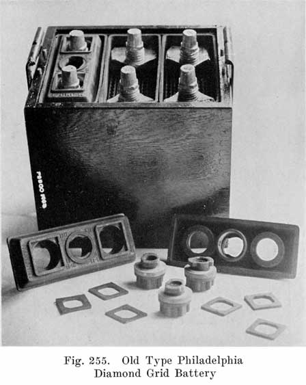
This construction increases the distance that the acid must travel along the post, in order to cause a leak, about two and one-half times the vertical distance on a smooth post. The hard rubber washer which fits around the post acts as a lock to prevent the post from turning. This applies especially to the two terminal posts to which the cables are attached. The washer is intended to prevent any strain in the cable from turning the post and breaking the seal between the post and the compound.
New Development in the Philadelphia Battery
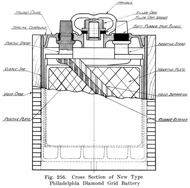
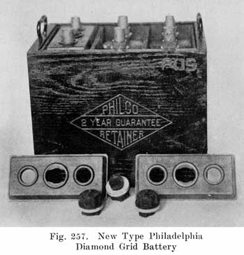
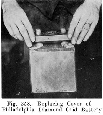
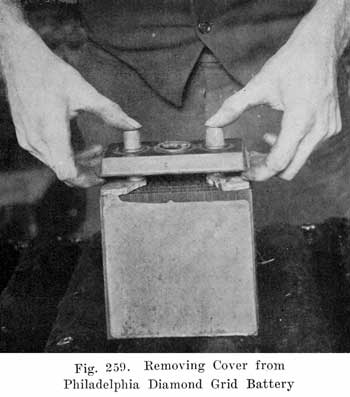
Rubber Lockt Seal Covers. During the last few years there has been a marked tendency in the battery industry to do away with the use of sealing compound for making a joint between the cell cover and the terminal posts and to substitute a mechanical seal of some kind at this joint. The Philadelphia Storage Battery Co. has developed the "Rubber Lockt". cover seal, the construction of which is shown in detail in Figs. 256 and 257. On the cell posts there is a. flange which supports the cover, and above this there is a recessed portion into which is slipped a soft rubber sleeve or bushing. This portion of the post is made with a ridge extending around the post and with the rubber sleeve forming a high point over which a corresponding locking edge in the terminal hole of the cover is snapped. This construction makes a joint which is flexible and at the same time acid tight. Vibration tends to push the cover down on the supporting flanges, as the post diameter is smaller below the locking edge. The design is simple, both from the assembly and the repair standpoint, as no tools are required for either operation. In the assembly operation the groups are lined up so that the post centers are correct and, after wetting the soft rubber sleeves, the cover is snapped in place with a quick downward push. See Fig. 258. In removing the covers, catch under each end with the fingers and pull upward, at the same time pressing with the thumbs on the top of the posts. See Fig. 259.
![]()
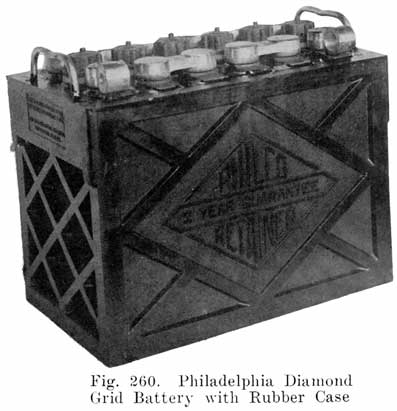
Rubber Case Batteries. Another development of recent years consists of the replacing of the wood case and rubber jars by a one-piece container of hard rubber with compartments for the elements The Philadelphia Storage Battery Co. has developed the Diamond Rubber case, which combines strength and lightness with an attractive appearance. See Fig. 260. One of the troubles experienced with the earlier designs of the rubber case was the bulging of the end, due to the pull of the battery hold down rod on a small handle attached to the center of the end. In the Philadelphia battery this has been overcome by the use of a wide handle which snaps into openings in the end of the case. in such a way that the pull on the handle is transferred to the sides. Another feature of this type handle is that it is a separate piece snapped into the case without the use of any metal insert in the rubber case, and if the handle should break, it can be replaced at small expense without the use of any tools.
The Philadelphia vent plug is of the bayonet type, and is tightened by a quarter turn. The plug simply has a small vent hole in the top, and may either be taken out or left on while battery is charging.
The Philadelphia separator is made of quarter sawed hardwood. It has a hard resinous wood in which the hard and soft portions occur in regular alternating vertical layers. The soft layers are porous, and permit the diffusion of the acid from plate to plate. The hard layers give the separator stiffness and long life. The alternating hard and soft layers are at right angles to the surface of the separator, so that the electrolyte has a direct path between plates.The methods of repairing Philadelphia Diamond Grid batteries are no different from those already given, on pages 328 to 374.
When the elements of the old type batteries have been assembled and returned to the jars, put the covers in place, and pour the compound around the edges of the cover, and in the post wells. The old compound must be removed from the petticoats on the posts before new compound is poured in. The compound must be warm and thin enough to flow around and fill up the petticoat spaces on the posts in order to get a good seal. When the post wells are full of compound, and while compound is still warm, put on the square sealing washers and press them down so that the holes in the washers fit closely around the octagonal part of the posts.
It is claimed by the manufacturers that the sulphate which forms in the Eveready battery during discharge always remains in the porous, convertible form, and never crystallizes and becomes injurious, even though the battery is allowed to stand idle on open circuit for a considerable length of time. Due to this fact, the Eveready battery is called a "Non-Sulphating Battery."The manufacturers state that Eveready batteries which have stood idle or in a discharged condition for months do not suffer the damages which usually result from such treatment, namely: buckling, and injurious sulphation. The plates do become sulphated, but the sulphate remains in the porous, non-crystalline state in which it forms. Charging such a battery at its normal rate is all that is necessary to bring it back to its normal, healthy condition. Due to the excessive amount of sulphate which forms when the battery stands idle or discharged for a long time, it is necessary to give the battery 50 percent overcharge to remove all the sulphate and bring the battery back to a healthy working condition. The colors of the plates are good guides as to their condition at the end of the charge. The positives should be free from blotches of white sulphate, and should have a dark brown or chocolate color. The negatives should have a bright gray or slate color.
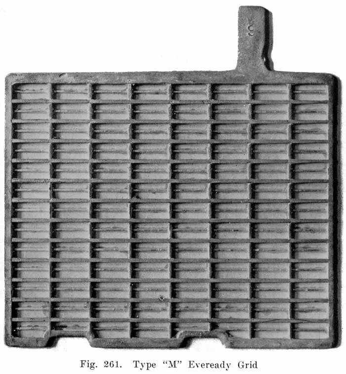
Eveready plates are of two general types. Plates of the R type are each provided with two feet on lower ends, the positive set and the negative set resting on two separate pairs of bridges in the jars, thereby preventing the sediment which accumulates on top of bridges from short circuiting a cell.Plates of the M type, instead of having feet, are cut away where they pass over the bridges of the opposite group. See Fig. 261. This construction secures a greater capacity for a given space, and gives the same protection against short circuit from sediment as the foot construction does, since the same amount of sediment must accumulate with either type of plate to cause a short circuit.
The separators used in Eveready batteries are made of cherry wood because it is a hard wood which will resist wear, is of uniform texture, even porosity, and has a long life in a given degree and condition of acid.Eveready cherry wood separators go to the repair man in a dry condition, as they do not require chemical treatment. Separators when received should be soaked in 1.250 specific gravity acid for four days or longer in order to expand them to proper size and remove natural impurities from the wood. After being fully expanded they should be stored moist as previously described. Stock separators may be kept indefinitely in this solution and can be used as required. Fig. 262 shows the top construction in the Eveready battery.
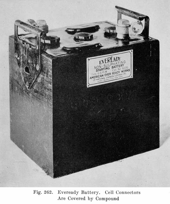
Cell connectors are heavily constructed and are sealed over solidly with a flexible sealing compound, Fig. 262. Two types of cell connectors are used-the crescent and the heavy or "three way" type.To properly open and re-assemble an Eveready battery, proceed as follows:
1. Take a hot putty knife and cut the compound from the top of each of the inter-cell connectors until the entire top of the connector is exposed.
2. Center punch tops of cell connectors and terminal posts.
3. Drill off cell connectors. In drilling off crescent cell connector use 1/2 inch drill, and for heavy type connector use 5/8 inch drill.
Drill deep enough, usually 3/8 to 1/2 inch, until a seam between connector and post is visible around lower edge of hole. Having drilled holes in both ends of connector, heat connector with soft flame until compound adhering to it becomes soft. Then take a 1/2 inch or 5/8 inch round iron or bolt, depending on connector to be removed, insert in one of the holes, and pry connector off with a side to side motion, being careful not to carry this motion so far as to jam connector into top of jar.
4. After connectors have been removed, steam and open the battery, as described on pages 332 to 335.
5. Examine plates, and handle them as described on pages 335 to 355. Remember, however, that Eveready plates which show the presence of large amounts of sulphate, even to the extent of being entirely covered with white sulphate, should not be discarded. A battery with such plates should be charged at the normal rate, and given a 50 percent overcharge.
6. Before re-assembling plate groups preparatory to assembling the battery, take negative and positive plate groups and build up the posts with the aid of a post builder to their original height.
Assemble groups in usual manner, taking care that posts on straps are in proper position relative to group in adjoining cell, so that cell connectors will span properly. Eveready batteries use a right and left hand strap for both positive and negatives, making it necessary to use only one length of cell connector.
7. After inserting assembled plate groups into battery in their proper relation as to polarity, heat rubber covers to make them fairly pliable and fit them over posts and into top of jar, pressing them down until they rest firmly on top of plate straps. See that covers are perfectly level and that vent tubes are perpendicular and all at same height above the plates.
8. Heat compound just hot enough so that it will flow. Pour first layer about one quarter inch thick, being careful to cover entire jar cover. Take a soft flame and seal compound around edges of jar and onto posts.
9. Now proceed to burn on top connectors. Cell connectors need only be cleaned in hole left by post, and top of each end.
10. While burning in cell connectors the first layer of compound will have cooled sufficiently to permit the second layer to be applied. This should be done immediately after burning on connectors and while they are still hot. Also heat the terminal posts, as compound will adhere to hot lead more readily than to cold.
Start second layer of compound by pouring it over cell connectors and terminal posts, first filling in with sufficient compound to bring level just above the tops of jars. Apply flame, sealing around edges of wood case, being particularly careful to properly seal terminal posts. Let this layer cool thoroughly before applying third layer.
11. The third layer of compound should be applied in the same way as second layer, pouring on connectors and terminal posts first, and filling in to the level of top of wood ease. The spaces between bars of cell connectors will fill and flow over properly if second layer has been allowed to cool and if cell connectors have not been burned up too high. In sealing last layer with flame, care should be taken not to play flame on compound too long as this hardens and burns the compound. Burned compound has no flexibility and will crack readily in service, thus causing the battery to become a "slopper." In pouring compound be sure to have battery setting level so that compound will come up even on all edges of case. Do not move battery after pouring last layer until thoroughly cool.
Before installing battery on car be sure that no compound, etc., has been allowed to get onto taper of terminal post, as this will make a poor connection. If this has happened, clean with medium grade sandpaper.
|
|
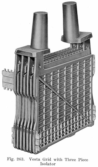
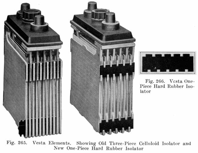
Vesta Isolators. The Vesta plate embodies in its design devices which are intended to hold the plates straight and thus eliminate the buckling and short-circuiting which form a large percentage of battery trouble. Fig. 263 shows clearly the construction of the old type of plate. Each isolator used in the old type of plate consists of two notched strips of celluloid, with a plain celluloid strip between them. The notches are as wide as the plates are thick, the teeth between the notches fitting into the spaces between plates, thus holding the plates at the correct distances apart. The plain celluloid strip holds the notched strips in place. At each corner of the Vesta plate is a slot into which the isolator fits, as shown in Fig. 263. Since the teeth on the two notched pieces of each. isolator hold the plates apart, they 'cannot "cut-out" or "short-out" by pinching through the wooden separators, or "impregnated mats" as they are called by the Vesta Company. |
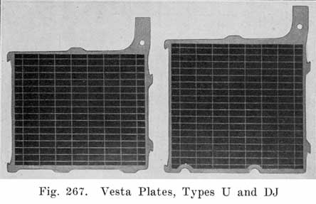
The appearance of a group of the new Type "D" construction is shown in Fig. 265, where Type "C" and Type "D" groups are illustrated side by side for purposes of comparison. It will be seen that the "D" isolator is of one piece only (shown separately in Fig. 266). The material is a heavy hard rubber stock which will be no more affected by acid or by electrical conditions in the cell than the hard rubber battery jar itself. The indentations on the two edges of isolator engage in hook shaped lugs on plate edges (Fig. 267 shows these clearly) and lock the plates apart fully as efficiently as the three-piece construction.
There are a number of important advantages which have been gained by the new method of isolation. The illustration (Fig. 265) shows how the "D" isolator permits the separators to completely cover and project slightly beyond the edges of the plates, whereas in the old construction there is an edge just above the isolators where the plates are not covered. This improvement means protection against shorts due to flaking, always so likely to occur during the summer "overcharging" season. Overcharging is, of course, a form of abuse, and Type "D" batteries are designed to meet this sort of service. Another great advantage gained is in the arrangement of lugs, It will be noted that the positive isolator hooks are in alignment, as are the negative hooks, but that these two rows, of opposite polarity, are separated from each other by the full width of the isolator; whereas in the Type "C" construction the outer edges of the plates, of opposite polarity, were separated only by the usual distance between plates.
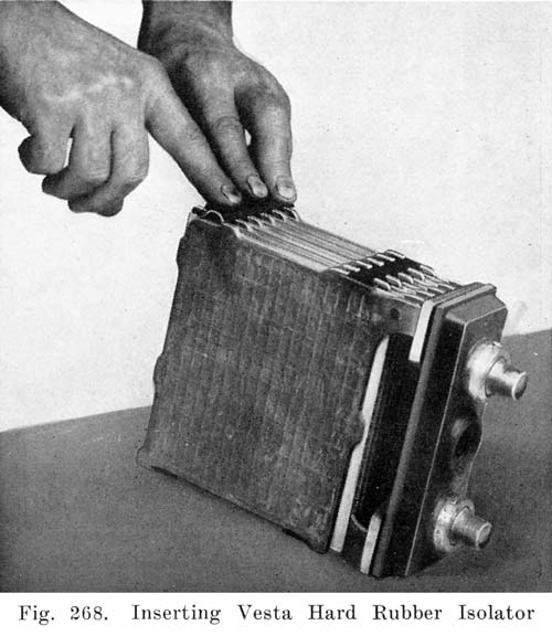
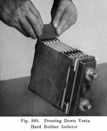
The new isolator is simple to insert and remove. Being made of hard rubber, it will soften and become pliable if a sufficient degree of heat is applied. The heat required is approximately 150° to 160°F., a temperature far above that reached by any battery cell, even under the most extravagant condition of abuse, but readily attained in the shop by means of a small flame of any kind-even a match will do in an emergency. The flame (which should be of the, yellow or luminous variety, as the blue flame tends to scorch the rubber) is played lightly over the isolator a few seconds. The rubber becomes soft and is then removed by inserting under the end of the isolator any narrow tool, such as a small screw driver, a wedge point, chisel, etc., and prying gently. In replacing isolators, a small hot plate is convenient but not at all necessary. The isolators are placed on the hot plate, or held in a luminous flame, until soft enough to bend. They are then bent into an arched shape, as shown in Fig. 268, and quickly fitted into place under the proper lugs. The regular isolator spacing tool is convenient and helpful in maintaining the plates at uniform intervals while this operation is carried out. The job is completed by pressing down the. still warm isolator with any handy piece of metal having a flat edge that will fit the distance between the lugs (Fig. 269). The shank of. a screw driver does splendidly for this work. . The pressure causes the isolator to straighten out, and the indentations fit snugly under the respective hooks on the plates. At the same time the contact with the cold metal chills the rubber to its normal hard condition. It is especially to be noted that the entire operation of isolator removal and replacement can be carried out with none but the commonest of shop tools.
![]()

All of the "U" size batteries have been changed to Type "D," so that all "CU" types are superseded by corresponding "DU's." Type "D" will not be used on cells of sizes "L," "H," or A, all of which remain of the "C" or three-piece isolator construction. Type "S" remains old style as before.
The Vesta Company has added a new plate size, produced in the "D" style (one-piece) isolator only, and known as "DJ."This plate is one-half inch higher than the "U," as shown in Fig. 267. It has 10 per cent more capacity. "DJ" batteries are available in all forms corresponding with "CU" types, and can be obtained by merely changing the type form name in ordering, as for example, to replace form 150, 6-DJ11-Y-150. The overall height of the completed battery is, of course, one-half inch more, and the "DJ" should therefore be ordered only when this additional height space is available in the battery compartment of the car.
The Vesta separators, or "mats," are treated by a special process. The Vesta Company considers its "mats" a very important feature of the battery. See page 15.
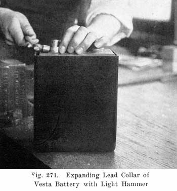
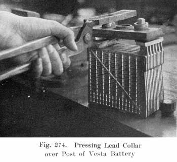
A lead collar fits over each post to hold the cover tight against the soft rubber gasket underneath. This collar is not screwed or burned on the post, but is simply pressed down over the post, depending. for its holding power upon the fact that two lead surfaces rubbing against each other tend to "freeze," and unite so as to become a unit. The connector rests upon the upper race of the collar, and also helps to hold it down in its proper position. Fig. 270 shows the complete battery with the lead collar, and the large vent plug.In rebuilding Vesta batteries having the lead collars, the cover should be left in place when working on the plates, if possible. If, however, it is necessary to separate groups, and the lead collars must be removed, this is done as shown in Fig. 271. A few blows on the side of the collar with a light, two ounce hammer expands the lead collar several thousands of an inch so that the collar may be removed.
![]()
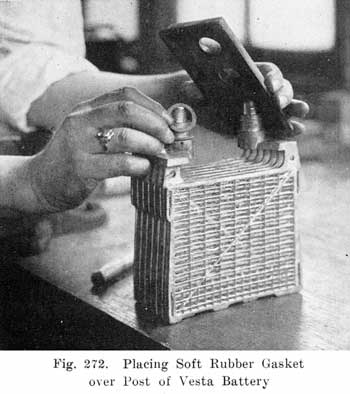
In replacing the covers, the lead collar must be forced down over the post, and special pressure tongs are required for this purpose. Before driving on the old collar, the post should be expanded slightly by driving the point-of a center-punch into the shoulder on the post. Instead of expanding the shoulder a new collar may be used.Fig. 272 shows the soft rubber gasket. being placed over the post, and shows the construction of the cover with its recess to fit the gasket.
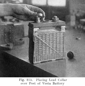
Fig. 273 shows the lead collar being placed over the post after the cover is in place.
Fig. 274 shows the special long lipped tongs required to force the collar down on the post shoulder. One lip of the tongs has a hole into which the post fits. The necessary driving force may be obtained by applying pressure to the ends of the lips of the tongs With an ordinary vise. This forces the cover down on the rubber gasket to make the acid-tight seal.
![]()
Westinghouse batteries have a special seal between covers and posts, as' shown in Fig. 275. A lead foundation washer (J) is set around the post. A "U" shaped rubber gasket, (K) is then forced between the cover and post, with the open end up. The lips of this gasket are tapered, with the narrow edge up. A tapered lead sleeve (L) is then forced between the lips of gasket (K), thereby pressing the inner lip against the post and the outer lip against the cover.
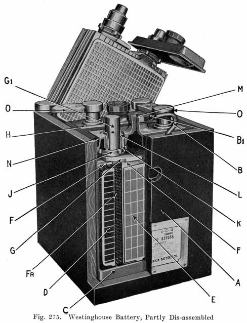
The lead sleeve is held in place by broaching or indenting the collar on taper lead sleeve into the posts.To break the seal, a hollow reamer or facing tool, fitted into a drill press or breast drill, is slipped over the post. A few turns will remove that part of the sleeve which has been forced into the post. Remove sealing compound around cover, remove group from cell. The cover can then be lifted off and if any difficulty is experienced, it can easily be removed by prying up cover with screwdriver. After removing the cover, the tapered lead sleeve and "U" shaped gasket can be removed. If these instructions are followed, the "U" shaped gasket and taper lead sleeves can be used when battery is reassembled.
With the addition of the foregoing instructions on the post seal, the standard directions for rebuilding batteries given on pages 328 to 374 apply to Westinghouse batteries.
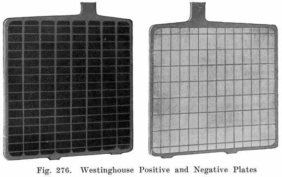
In any given size, the Westinghouse battery has two more plates per cell than the usual 1/8 inch plate battery. It has the same number of plates as the 3/32 inch thin plate battery, but the thickness of the plates is about half-way between the 1/8 inch and 3/32 inch plates.The Westinghouse negative grids, Fig. 276, have very few and small bars, just enough to hold the active material. It is slightly thinner than the positive but has the same amount of active material, due to the design of the grids. The condition of Westinghouse negatives should not be determined by cadmium readings as these plates may be fully charged and yet not give reversed cadmium readings.
Aside from the special instructions given for the Westinghouse Post Seal, the Standard Instructions for Rebuilding Batteries, given. on pages 328 to 374 may be used in rebuilding Westinghouse batteries.
TYPES OF WESTINGHOUSE BATTERIES
The type "A" series was designed to fit the battery compartment in certain rather old models of cars. Owing to a lack of space this series is not of as efficient design as the "C " and "B" series. It does have the Westinghouse Post Seal, however.Type "A" batteries are not recommended for use when "B" or "C" batteries can be used.
Type
Part No.
Ampere
Hours
at Usual
Lighting Rate
Ampere
Rate for
20 Minutes
Ampere
Rate for
5 Hours
Length in
Inches
L
Weight
in Pounds
6-A-11
100071
64
68
9.1
8
38
6-A-13
100072
79
82
11.0
9-1/8
42
6-A-15
100073
94
96
12.8
10-1/4
46
6-A-17
100074
109
109
14.6
11-9/16
52
6-A-21
100075
139
136
18.2
14-3/16
63
6-A-25
100076
169
164
22.0
17
75
12-A-7
100077
34
41
5.5
10-7/16
48
12-A-11
100078
64
68
9.1
14-15/16
70
12-A-17
100079
109
109
14.6
22-1/16
102
(The above is typical of the of previous charts that were omitted, very typical of following omitted charts.)
Plates
|
Width |
Height |
Thickness |
|
5-5/8 |
4-1/8 |
.098 |
The type "B" series of batteries has been designed for use on a number of cars now in service that do not have a sufficient headroom in the battery compartment for type "C." Type "B" batteries carry all of the features of the type "C." Due to the fact that the plates of necessity must be somewhat shorter than in the type "C" batteries their efficiency from the point of ampere hours per pound of weight is slightly less than the type "C" series.
(Chart omitted.)
Plates
|
Width |
Height |
Thickness |
|
5-5/8 |
4-3/4 |
0.1 |
The type "C" series of batteries is the Westinghouse standard. The outside dimensions and capacity are such that some one of this design may be used in a majority of cars now in service. The Westinghouse design was built around this type and it should be used for replacement or new equipment.Type "C" batteries are provided with the Westinghouse Post Seal wherever possible.
(Chart omitted.)
Plates
|
Width |
Height |
Thickness |
|
5-5/8 |
4-1/4 |
0.1 inch |
The type "E" series was designed for replacement work on a few old model cars now in service where a narrow, high battery was necessary. The design is not as efficient as the "B" and "C" lines, due to a lack of space and further, it has been necessary to omit the Westinghouse Post Seal for the same reason.
(Chart omitted.)
Plates
|
Width |
Height |
Thickness |
|
4-1/8 |
5-5/8 |
.098 |
The type "H" battery is built with heavier plates than the type "C" and "B" batteries for use in cars where the necessary increased space is available and where the weight per ampere output is not a consideration. Under the same -use the battery will give a greater life than the type "C" or "B" battery having the same positive area.This battery has a greater space between the plates than the "C" or "B" battery and will therefore have less internal discharge when standing on open circuit, and is more desirable for miscellaneous use where open circuit discharge is of consideration.
(Chart omitted.)
Plates
|
Width |
Height |
Thickness |
|
5-5/8 |
5 |
.19 |
The type "J" battery is an extremely heavy construction battery with thick plates, and it was designed primarily for use on trucks and other vehicles of this type where there is excessive vibration and other possibility of mechanical abuse. This battery will give a greater life than either the "H", "C" or "B" battery with the same plate -area. It is provided with wood separators and rubber sheets.This battery has a greater space between the plates than the "C" or "B" battery and will therefore have less internal discharge when standing on open circuit, and is more desirable for miscellaneous use where open circuit discharge is of consideration.
(Chart omitted.)
Plates
|
Width |
Height |
Thickness |
|
5-5/8 |
5 |
.19 |
The "0" type battery sacrifices some capacity in obtaining a rugged strength. It is a special battery made only with nineteen plates per cell where the percentage of sacrificed capacity is not great as compared with the twenty-one plate "C" type. It fills the same space as does a 6-C-21. It has greater life and strength. It has less capacity but it is built for conditions requiring less capacity than a twenty-one plate cell.
(Chart omitted.)
Plates
|
Width |
Height |
Thickness |
|
5-5/8 |
5-1/4 |
.123 |
There is only one type "F" battery. It is of big heavy construction exactly the same dimensions as the battery used for a number of years on the Cadillac and certain other cars. This battery is heavier than type "C" of the same capacity and it has a greater life.(Chart omitted.)
Plates
|
Width |
Height |
Thickness |
|
4-3/4 |
5-1/4 |
.17 |
WILLARD BATTERIESSince 1912, when the Willard Storage Battery Co. began to manufacture storage batteries for starting and lighting work, various types of Willard batteries have been developed. The original Willard starting and lighting batteries used two-piece, or "double" covers. These are shown in the cuts used to illustrate the sealing of double-cover covers in the preceding chapter, and no further description will be given here. The doublecover batteries are no longer made, but the repairman will probably be called upon to repair some of them. The instructions given in the preceding chapter should be used in making such repairs.
Following the double cover batteries came the single cover battery, of which a number of types have been made. One type used a rectangular post, and was very difficult to repair. Fortunately, this type was not used extensively, and the battery is obsolete.
Willard Batteries With Compound Sealed Posts
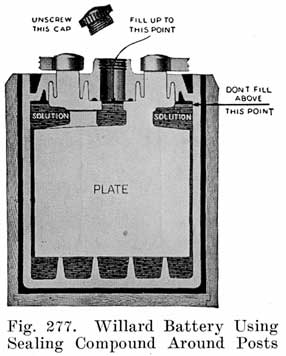
The oldest type single-cover Willard battery which the repairman will be called upon to handle is the compound sealed post type, illustrated in-Fig. 277. This battery includes types SEW, SER, SJW, SL, SLR, SM, SMR, STR, SXW, SXR, SP, SK, SQ, EM, and EMR. As shown in Fig. 277, there is a well around each post which is filled with: sealing compound. On the under side of the cover is a corresponding well which fits into the post well, the sealing compound serving to make the seal between the cover and the post.
|
|
Aside from this post seal, no special instructions are required in rebuilding this type of Willard battery. A 3/4 inch drill is needed for drilling off the connectors. When the plates have been lifted out of the jars, and are resting on the jar to drain, and while- the compound and cover are still hot, remove the cover by placing your fingers under it and pressing down on the posts with your thumbs. |
Willard Batteries With Lead Inserts In Covers
The types SJWN and SJRN Willard batteries have lead inserts in the cover post holes, as shown in Mg. 278, the inserts being welded to the posts. For removing the connectors and for separating the post from the cover insert, the Willard Company furnishes special jigs and forms. The work may also be done without these jigs and forms, as will be described later.When the special jigs and forms are used, the work is done, as follows:
1. Place Willard drill jig Z-72 (Fig. 279) over the connector, and with a 13/16 inch drill, bore down far enough to release the connector from the post (Fig. 279).
2. File off the post stub left by drilling. This will give a flat surface on top of the cover insert and will make it easier to center the drill for the next operation.3. With a 57/64 inch drill, and Willard jig Z-94 (Fig. 280), drill down to release the post from the cover insert.
4. In reassembling, build the post up to a height of 1-5/16 inches above the top of the plate strap, using Willard post builder Z-93 (Fig. 281).5. After removing the post builder, bevel the top edge of the post with a file, as indicated at "A" (Fig. 281). Then replace plates in the jars.
6. File off tops of cover inserts at "A" (Fig. 282), to a height of 3/16 inch above the cover. Also remove any roughness on surface "B" caused by pliers when cover was removed.
7. Put on the covers so that their tops will be 1/32 inch above the top edge of the jars, tapping them lightly with a small hammer.8. Place Willard burning form Z-87 (Fig. 283) over the post and cover insert and burn the post to the insert.
9. Remove form Z-87 and thoroughly brush off the top of the post stub. Then build up the stub post, using Willard burning form Z-88 on the positive posts and form Z-89 on the negative posts (Fig. 284).
10. Now seal the covers with sealing compound as usual, and burn on the connectors.11. If the terminal posts are made for clamp terminals, build up the posts by using Willard burning form Z-90, for the positive posts and Z-91 for the negative posts (Fig. 285).
To work on the post seals of Willard types SJWN and SJRN without the special Willard jigs and forms:1. Remove the connectors and terminals as usual.
2. Saw off the posts close to the covers, taking care not to injure the covers; This will separate the posts from the cover inserts, and the covers may be removed.
3. In reassembling, Ale off the top of the cover insert at "A" (Fig. 292).
4. Put covers on so that their tops will be 1/32 inch above the top edge of the jars, tapping the covers lightly with a small hammer.
5. Brush the top of post and cover insert perfectly clean. Now make a burning form consisting of a ring 1-1/8 inside diameter and 1-5/8 inch outside diameter and 3/16 to 1/4 inch high. Set this over the stub post and cover. With a hot lead burning flame melt the top of the post and cover insert together. Then melt in lead up to the top of the special burning form (Fig. 286). Then remove the form.
6. Set post builders on the part of the posts which has been built up and build up the posts as usual, Fig. 286. Then burn on the connectors and terminals.
Fig. 287 shows this type of construction, used on types SJRG and SLWG. Fig. 288 shows the seal in detail. A soft rubber gasket is slipped over the post, and the cover is pushed down over the gasket. For removing the covers, have a cover removal frame made as shown in Fig. 289. Fasten the frame to a solid wall or bench so that it will withstand a strong pull. In rebuilding this type of battery proceed as follows:
1. Drill off the connectors and terminals, leaving the post stubs, as high as possible, since the only way of removing the plates is by grasping the post stubs with pliers.
2. Steam the battery to soften the sealing compound and lift out the plates as usual.3. To remove covers. Saw the post stubs off flush with the covers. Place the element in the cover removal frame (Fig. 289) and pull steadily on the element. A little swaying motion from side to side may help in loosening the covers. If any of the gaskets remain on the posts when the covers are removed, replace them in the cover and thoroughly dry the inside with a rag.
4. To replace covers. With a rag or tissue paper wipe off the posts and then dry them thoroughly with a soft flame.With a 3/4 inch bristle bottle brush apply a thin coating of rubber cement to the inside surfaces of the gaskets. Do this to one cover at a time and apply the cover quickly before the cement dries. The cement acts as a lubricant, and without it, it will be impossible to replace the covers.
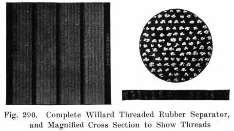
Fig. 290 shows the Willard Threaded Rubber Separator which is made of a rubber sheet pierced by thousands of threads which are designed to make the separator porous. This separator is not injured by allowing it to become dry, and makes it possible for the Willard Company to ship its batteries fully assembled without electrolyte or moisture, the parts being "bone-dry."
Types. The Universal Battery Co. manufactures batteries for (a) Starting and Lighting, (b) Lighting, (c) Ignition, (d) Radio, (e) Electric Cars and Trucks, (f) Isolated, or Farm Lighting Plants, and (g) General Stationary Work.Construction Features. The Universal Starting and Lighting Batteries embody no special or unique constructions. The boxes are made of hard maple, lock cornered and glued. The jars have single rubber covers. The separators are made of Port Orford white cedar wood, this wood being the same as that used in some of the other standard makes of batteries. The space between the covers and connectors is- sufficient to permit lifting the battery by grasping the connectors.
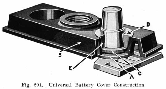
Fig. 291 shows the Universal Co. Post Seal construction. A soft rubber washer (A) is first slipped over the post. The cover (B) is then put in place, and rests on the washer (A) as shown. A second washer (C) is then slipped over the post, resting on the upper surface of the shoulder of the cover. The lead sleeve washer (D) is then forced down over the post, pressing washer (C) down on the cover, and pressing the cover down on washer (A). The two rubber washers serve to make a leak proof joint between post and cover. The lead sleeve-washer (D) "freezes" to the post, and holds cover and washers in position.In rebuilding Universal batteries the cover need not be removed unless it is desired to replace plate groups. To remove the cover, after the cell connectors have been drilled off, drill down through the post-stub until the drill has penetrated to the shoulder (E). This releases the seal and the cover may be lifted off. To save time, the post-stub may be cut off flush with the top of the cover with a hack saw after the cell connectors have been drilled off. The drill is then used as before to release the grip of the washer. Using a drill to release the grip of the washer makes it necessary to build up the posts when the battery is reassembled. Instead of using an ordinary twist drill, a special hollow drill may be obtained from the Universal Battery Co. This drill cuts away the lead sleeve gasket without injuring the post. If an ordinary drill is used, a 3/4 inch drill is required for the seven plate battery and a 13/16 inch drill for all other sizes.
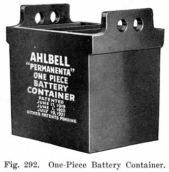
ONE-PIECE BATTERY CONTAINERS
The standard practice in battery assembly has always been to place the plates of each cell in a separate, hard rubber jar, the jars being set in a wooden box or case. Each six-volt battery thus has four containers. When a wooden case is used, jars made of rubber, or some other nonporous, acid-resisting material are necessary.
|
|
Wooden cases have been fairly well standardized as to the kinds of wood used, dimensions, constructional features, and to a certain extent, the handles. The disadvantage of both the wooden case and the iron handles is that they are not acid proof. Acid-proof paint protects them from the action of the acid to a certain extent, but paint is easily scraped off, exposing the wood and iron to the action of the acid. It is practically impossible to prevent acid from reaching the case and handles, and corroded handles and rotted cases are quite common. |
The repairman should not overlook the possibilities of the one-piece containers. In making up rental batteries, or in replacing old cases, the one-piece containers may be used to advantage. These containers are suitable for Radio batteries, since they have a neater appearance than the wooden cases, and are not as likely to damage floors or furnishings because the acid cannot seep through them.
The Titan Battery is built along standard lines, as far as cases, plates, separators, and jars are concerned. The ribs of the grids not arranged at right angles but are arranged as shown in Fig. 293. Each pellet of active material is supported by a diagonal rib on the opposite face of the grid.
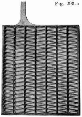
The Titan Post Seal is shown in Fig. 293. A soft rubber gasket (G) is slipped over the post, and rests on a shoulder (F) on the post. The cover has a channel which fits over the gasket and prevents the gasket from being squeezed out of place when the cover is forced down on the gasket. The post has two projections (DD), as shown, the lower surface of each of which is inclined at an angle to the horizontal. A lock nut (H), which has corresponding projections (IJ) is slipped over the post as shown at (0), and is given a quarter turn. The top surfaces of the projections on the lock-nut are inclined and as the locknut is turned, the projections on the post and nut engage, and the cover is forced down on the gasket (G). To lock the nut in place, a lock washer (L) is then slipped over the post, the projections (MM) fitting into spaces (KK) between the projections on the post and nut, thus preventing the nut from turning. A special wrench is furnished for turning the lock-nut. The cell connectors rest on the tops of the lock washers and keep them in place.The overhauling of Titan batteries should be done as described on pages 328 to 374.
|
|
|
| |||||||||