SECTION III
CHAPTER 17
FARM LIGHTING BATTERIES
Although the large Central Station Companies are continually extending their power lines, and are enlarging the territory served by them, yet there are many places where such service is not available. To meet the demand for electrical power in these places, small but complete generating plants have been produced by a number of manufacturers. These plants consist of an electrical generator, an engine, to drive the generator, and a storage battery to supply power when the generator is not running. The complete plants are called "House Lighting," "Farm Lighting," or "Isolated" plants.The batteries used in these plants differ considerably from the starting batteries used on automobiles. The starting battery is called upon to deliver very heavy currents for short intervals. On the car the battery is always being charged when the car is running at a moderate speed or over. The battery must fit in the limited space provided for it on the car, and must not lose any electrolyte as the car jolts along over the road. It is subjected to both high and low temperatures; and is generally on a car whose owner often does not know that his car has such a thing as a battery until his starting motor some day fails to turn over the engine. All starting batteries have wooden cases (some now use rubber cases), hard rubber jars, and sealed on covers. The case contains all the cells of the battery. Automobile batteries have, therefore, become highly standardized, and to the uninformed, one make looks just like any other.
Farm lighting batteries, on the other hand, are not limited as to space they occupy, are not subjected to irregular charging and discharging, do not need leak proof covers, and are not called upon to delivery very heavy currents for -short periods. These facts are taken advantage of by the manufacturers, who have designed their farm lighting batteries to give a much longer life than is possible in the automobile battery. As a result the farm lighting battery differs from the automobile battery in a number of respects.
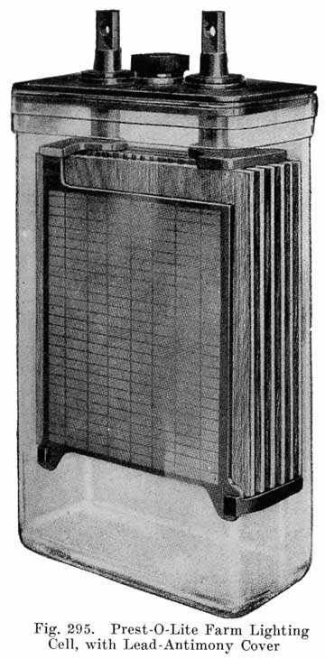
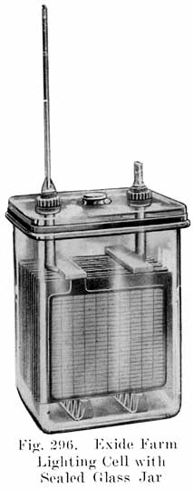
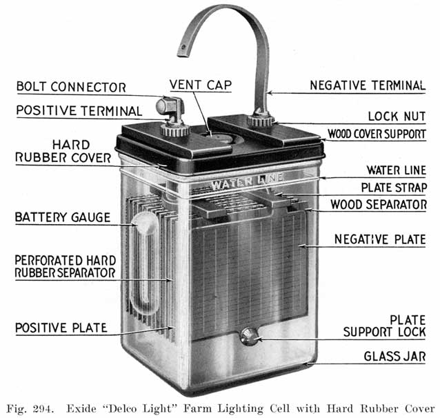
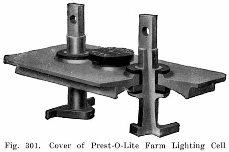
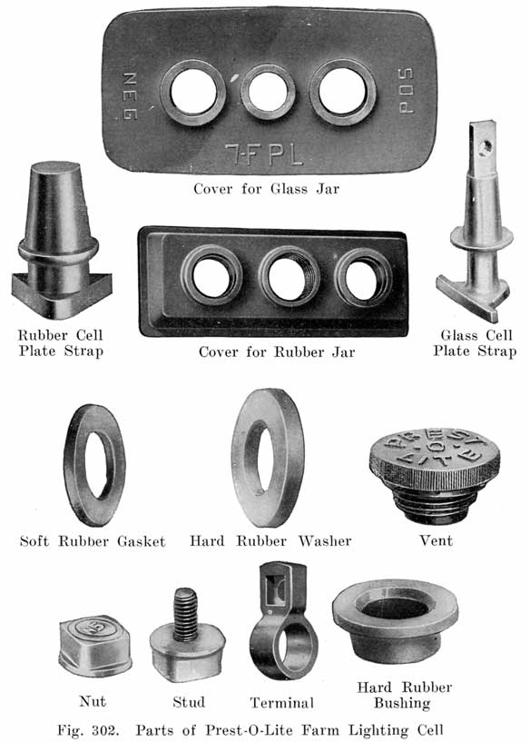
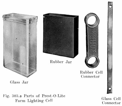
Jars. Both glass and rubber are used for farm lighting battery jars, and they may or may not have sealed-in covers. Fig. 294 shows a glass jar of an Exide battery having a hard rubber cover, and Fig. 295 shows a Prest-O-Lite glass jar cell having a cover made of lead and antimony. Unsealed glass jars, such as the Exide type shown in Fig. 324, generally have a plate of glass placed across the top to catch acid spray when the cell is gassing. Each jar with its plates and electrolyte forms a complete and separate unit which may easily be disconnected from the other cells of the battery by removing the bolts which join them. In working on a farm lighting battery, the repairman, therefore, works with individual cells instead of the battery as a whole, as is done with automobile batteries.
Batteries with sealed jars are generally shipped completely assembled and filled with electrolyte, and need only a freshening charge before being put into service, just as automobile batteries which are shipped "wet" are in a fully charged condition when they leave the factory and need only a charge before being installed on the car.
|
|
|
Farm lighting battery jars are less liable to become cracked than those of automobile batteries because they are set in one place and remain there, and are not jolted about as automobile batteries are. Cracked jars in farm lighting batteries are more easily detected as the jar will be wet on the outside and the acid will wet the shelf or sand tray on which the jar rests.Batteries with sealed rubber jars are normally assembled four cells in a case or tray, with a nameplate on each tray which gives the type and size of cell. The cells are connected together with lead links which are bolted to the cell posts by means of lead covered bolt connectors.
|
|
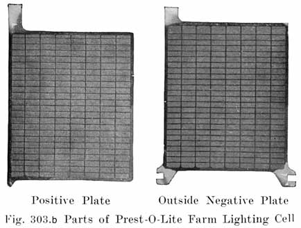
Plates. Since farm lighting batteries are not required to deliver very heavy currents at any time, the plates are made thicker than in starting batteries. this giving a stronger plate which has a longer life. than the starting battery plate. |
Electrolyte. In a starting battery the specific gravity of the electrolyte of a fully charged cell is 1.280-1.300, no matter what the make of the battery may be. In farm lighting batteries, the different types have different values of specific gravity when fully charged. The usual values are as follows:(a) Batteries with sealed glass jars 1.210 to 1.250(b) Batteries with open glass jars 1.200 to 1.250
(c) Batteries with sealed rubber jars 1.260 to 1.280
A brief discussion of specific gravity might be helpful at this point. In any lead acid battery current is produced by a chemical action between the active material in the plates and the water and sulphuric acid in the electrolyte. The amount of energy which can be delivered by the battery depends on the amount of active material, sulphuric acid, and water which enter into the chemical actions of the cell. As these chemical actions take place, sulphuric acid is used up, and hence there must be enough acid contained in the electrolyte to enter into the chemical actions. The amount of water and acid in the electrolyte may be varied, as long as there is enough of each present to combine with the active material of the plates so as to enable the cell. to deliver its full capacity. Increasing the amount of acid will result in the plates and separators being attacked and injured by the acid. Increasing the amount of water dilutes the acid, giving a lower gravity, and preventing the Acid from injuring plates and separators. This results in a longer life for the battery, and is a desirable condition. In starter batteries, there is not enough space in the jars for the increased amount of water. In farm lighting batteries, where the space occupied by the battery is not so important, the jars are made large enough to hold a greater amount of water, thus giving an electrolyte which has a lower specific gravity than in starting batteries.
Take a fully charged. cell of any starting battery. It contains a set of plates and the electrolyte which is composed of a certain necessary amount of acid and a certain amount of water. If we put the plates of this cell in a larger jar, add the same amount of acid as before, but add a greater amount of water than was contained in the smaller jar, we will still have a fully charged cell of the same capacity as before, but the specific gravity of the electrolyte will be lower.
Charging Equipment. Automobile batteries are being charged whenever the car is running at more than about 10 miles per hour, regardless of what their condition may be.
In farm lighting outfits, the charging is under the control of the operator, and the battery is charged when a charge is necessary. There is, therefore, very much less danger of starving or overcharging the battery. The operator must, however, watch his battery carefully, and charge it as often as may be necessary, and not allow it to go without its regular charge.
The generator of a farm lighting outfit is usually driven by an internal combustion engine furnished with the outfit. The engine may be connected to the generator by a belt, or its shaft may be connected directly to the generator shaft. A switchboard carrying the necessary instruments and switches also goes with the outfit. The charging of farm lighting batteries is very much like the charging of automobile batteries on the charging bench, except that the batteries are at all times connected to switches, by means of which they may be put on the charging line.
Some plants are so arranged that the battery and generator do not provide current for the lights at the same time, lights being out while the battery is charging. In others the generator and battery, in emergency, may both provide current. In others the lights may burn while the battery is being charged; in this case the battery is sometimes provided with counter-electromotive force cells which permit high enough voltage across the battery to charge it and yet limit the voltage across the lamps to* prevent burning them out or shortening their life. In some cases the battery is divided into two sets which are charged in parallel and discharged in series.
Relation of the Automobile Storage Battery Man to the Farm Lighting Plant. Owners and prospective owners of farm lighting plants generally know but little about the care or repair of electrical apparatus, especially batteries, which are not as easily understood as lamps, motors or generators. Prospective owners may quite likely call upon the automobile battery repair man for advice as to the installation, operation, maintenance, and repair of his battery and the automobile battery repairman should have little trouble in learning how to take care of farm lighting batteries. The details in which these batteries differ from starting batteries should be studied and mastered, and a new source of business will be opened.
Farm lighting plants in the vicinity should be studied and observed while they are in good working order, the details of construction and operation studied, the layout of the various circuits to lamps, motors, heaters, etc., examined so as to become familiar with the plants. Then When anything goes wrong with the battery, or even the other parts of the plant, there will be no difficulty in putting things back in running order.
"Farm Lighting Plant" is the name applied to the small electric plant to be used where a central station supply is not available. Such a plant, of course, may be used for driving motors and heating devices, as well as operating electric lights, and the plant is really a "Farm Lighting and Power Plant."Make. There are several very good lighting plants on the market and the selection of the make of the plant must be left to the discretion of the owner, or whomever the owner may ask for advice. The selection will depend on cost, whether the plant will fill the particular requirements, what makes can be obtained nearby, on the delivery that can be made, and the service policy of the manufacturer.
Type. Plants are made which come complete with battery, generator, engine, and switchboard mounted on one base. All such a plant requires is a suitable floor space for its installation. Other plants have all parts separate, and require more work to install. With some plants, the generator and engine may be mounted as a unit on one base, with battery and switchboard separate.
The type of jar used in the battery may influence the choice. Jars are made of glass or rubber. The glass jars have sealed covers, or have no covers. The rubber jars generally have a sealed cover. The glass jar has the advantage that the interior may be seen at all times, and the height of the electrolyte and sediment may be seen and the condition of the plates, etc., determined by a simple inspection. This is an important feature and one that will be appreciated by the one who takes care of the battery. Jars with sealed covers, or covers which although not sealed, close up the top of the jar completely have the advantage of keeping in acid spray, and keeping out dirt and impurities. Open jars are generally set in trays of sand to catch electrolyte which runs down the outside walls of the jars. The open jars have the advantage that the plates are very easily removed, but have the disadvantage that acid spray is not kept in effectually, although a plate of glass is generally laid over part of the top of the jar, and that dirt and dust may fall into the jar.
Size. The capacity of storage battery cells is rated in ampere hours, while power consumed by lights, motors, etc., is measured in watt hours, or kilowatt hours. However, the ampere hour capacity of a battery can be changed to watt hours since watt hours is equal to
Watt hours = ampere hours multiplied by the volts
If we have a 16 cell battery, each cell of which is an 80 ampere hour cell, the ampere hour capacity of the entire battery will be 80, the same as that of one of its cells, since the cells are all in series and the same current passes through all cells. The watt hour capacity of the battery will be 32 times 80, or 2560. The ampere hour capacity is computed for the 8 hour rate, that is, the current is drawn from the battery continuously for 8 hours, and at the end of that time the battery is discharged. If the current is not drawn from the battery continuously for 8 hours, but is used for shorter intervals intermittently, the ampere hour capacity of the battery will be somewhat greater. It seldom occurs that in any installation the battery is used continuously for eight hours at a rate which will discharge it in that time, and hence a greater capacity is obtained from the battery. Some manufacturers do not rate their batteries at the 8 hour continuous discharge rate but use the intermittent rate, thus rating a battery 30 to 40 percent higher. Rated in this way, a battery of 16 cells rated at 80 ampere hours at the 8 hour rate would be rated at 112 ampere hours, or 3584 watt hours.
In determining the size of the battery required, estimate as nearly as possible how many lamps, motors, and heaters, etc., will be used. Compute the watts (volts X amperes), required by each, Estimate how long each appliance will be used each day, and thus obtain the total watt hours used per day. Multiply this by 7 to get the watt hours per week. The total watt hours required in one week should not be equal to more than twice the watt hour capacity of the battery (ampere hours multiplied by the total battery voltage) at the eight hour. rate. This means that the battery should not require a charge oftener than two times a week.
The capacity of a battery is often measured in the number of lamps it will burn brightly for eight hours. The watts consumed by motors, heaters, etc., may be expressed in a certain number of lamps. The following table will be of assistance in determining the size of the battery required:
|
No. |
Type of Appliance |
Watts Consumed |
Equivalent Number of 20 Watt Lamps |
|
1 |
16 candle power, Mazda lamp |
20 |
1 |
|
2 |
12 candle power, Mazda lamp |
115 |
3/4 |
|
3 |
Electric Fan, small size |
75 |
4 |
|
4 |
Small Sewing machine motor |
100 |
5 |
|
5 |
Vacuum cleaner |
160 |
8 |
|
6 |
Washing machine |
200 |
10 |
|
7 |
Churn, 1/6 h.p. |
200 |
10 |
|
8 |
Cream Separator 1/6 h.p. |
200 |
10 |
|
9 |
Water pump 1/6 h.p, |
200 |
10 |
|
10 |
Electric water heater, small |
350 |
18 |
|
11 |
Electric toaster |
525 |
26 |
|
12 |
Electric stove, small |
600 |
30 |
|
13 |
Electric iron |
600 |
30 |
|
14 |
Pump, 1/2 h.p. |
600 |
30 |
From the foregoing table we can determine the current consumption of the various appliances:
|
No. |
Watts |
Amps. at 32 Volts |
Amps. at 110 Volts |
|
1 |
20 |
0.625 |
0.18 |
|
2 |
15 |
0.47 |
0.14 |
|
3 |
75 |
2.34 |
6.80 |
|
4 |
100 |
3.125 |
0.90 |
|
5 |
160 |
5.00 |
1.44 |
|
6 |
200 |
6.25 |
1.80 |
|
7 |
200 |
6.25 |
1.80 |
|
8 |
200 |
6.25 |
1.80 |
|
9 |
200 |
6.25 |
1.80 |
|
10 |
350 |
11.00 |
3.20 |
|
11 |
525 |
16.4 |
4.77 |
|
12 |
600 |
18.75 |
5.40 |
|
13 |
600 |
18.75 |
5.40 |
|
14 |
600 |
18.75 |
5.40 |
|
(Omitted, two simple charts that show how long "32-Volt Battery" and "110-Volt Battery" will carry various currents continuously.) |
The various appliances should be placed as near to each other as possible. The lights, of course, must be placed so as to illuminate the different rooms, barns, etc., but the power devices should be placed as close as possible to each other and. to the plant. The purpose of this is to use as little wire as possible between the plant and the various appliances so as to prevent excessive voltage drop in the lines.The wires leading to the various appliances should be large enough so that not more than one or two volts are lost in the wires. To obtain the resistance of the wire leading to any appliance, use the following equation:
![]()
Knowing the resistance of the wire, and the total length of the two wires leading from the plant to the appliance, the size of the wire may be obtained from a wiring table.Rubber insulated copper wire covered with a double braid should preferably be used, and the duplex wire is often more convenient than the single wire, especially in running from one building to another. Wiring on the inside of buildings should be done neatly, running the wires on porcelain insulators, and as directly to the appliance as possible. The standard rules for -interior wiring as to fuses, soldering joints, etc., should be followed.
(See also special instructions for the different makes, beginning page 460.)The room in which the plant is installed should be clean, dry, and well ventilated. It should be one which is not very cold in winter, as a cold battery is very sluggish and seems to lack capacity. If possible, have the plant in a separate room in order to keep out dirt and dust. If no separate room is available, it is a good plan to build a small room in a corner of a large room. Keep the room clean and free of miscellaneous tools and rubbish.
If the entire plant comes complete on one base, all that is necessary is to bolt the base securely to the floor, which should be as nearly level as possible. If the battery is to be installed separately, build a rack. Give the rack several coats of asphaltum paint to make it acid proof. The location of the battery rack should be such that the rack will be:
(a) Free from vibration.(b) At least 3 feet from the exhaust pipe of engine.
(c) Far enough away from the wall to prevent dirt or loose mortar from dropping on the cells.
Figs. 298 and 299 illustrate two types of battery racks recommended for use with farm light batteries. The stair-step rack is most desirable where there is sufficient room for its installation. Where the space is insufficient to make this installation, use the two-tier shelf rack. The racks should be made from 1-1/2 or 2 inch boards.
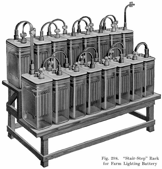
The cells may be placed on the battery rack with either the face or the edges of the plates facing out. The latter method requires a shorter battery rack and is very desirable from the standpoint of future inspections. In very dark places, it is more desirable to have the surface of the plates turned out to enable the user-to see when the cells are bubbling during the monthly equalizing charge. Either method is satisfactory.All metal parts such as pipes, bolt heads, etc., which are near the battery should be given at least three coats of asphaltum paint. Care must be taken not to have an open flame of any kind in the battery room, as the hydrogen and oxygen gases, given off as a battery charges may explode and cause injury to the person and possible severe damage to the battery. When making an installation, it is always a good plan to carry' the following material for taking care of spillage and broken jars:
- 1 Thermometer
- 2 Series Cells
- 6 Battery Bolts and Nuts
- 1 Hydrometer Syringe
- 2 Gallons distilled water
- 1 Jar Vaseline
- 1 Gallon 1.220 specific gravity electrolyte
When a battery arrives at the shipping destination, the person lifting this shipment should remove the slats from the top Of each crate and inspect each cell for. concealed damage, such as breakage: Should any damage be discovered, it is important that a notation covering this damage be made and signed by the freight agent on the freight bill. This will enable the customer or dealer to make a claim against the railroad for the amount of damage. If a notation of this kind is not made before the battery 'is lifted, the dealer will be forced to stand the expense of repairing or replacing the damaged cells.When removing cells from a crate, avoid lifting them by the terminal posts as much as possible. This causes the weight of the electrolyte and jar to pull on the sealing compound between the jar and cover, and if the sealing is not absolutely tight, the jar and electrolyte may fall from the cover. A cell should never be carried using the terminal posts as handles. The hand should be put underneath the jar.
Sometimes a battery will arrive with electrolyte spilled from some of the cells. If spillage is only about one-half to one inch down on the plates of three or four cells, this spillage may be replaced by drawing a little electrolyte out of each cell of the other full cells in the set. Oftentimes several cells will have electrolyte extending above the water line, which will aid greatly in making up any loss in other cells. After all cells have been drawn on to fill up the ones that are spilled, the entire set may then have its electrolyte brought up to the water line by adding distilled water.
Very carefully adjust spillage of pilot cells (Delco), as it is very important that the specific gravity 'of the pilot cells be left as near 1.220 as possible.
In case the spillage is more than one inch below the top of plates or glass broken, remove cell and install a new cell in its place. The spilled or broken cell must not be used until given special treatment.
Connecting Cells
Before connecting up the cells the terminals should be scraped clean for about 11/2 inches on both sides. An old knife or rough file is suitable for doing this work. After the terminals are thoroughly brightened, they should be covered with vaseline. The bolts and nuts used in making the connections on the battery should also be coated with vaseline. The vaseline prevents and retards corrosion, which is harmful to efficient operation.If a new battery is to be installed in parallel with one already in service, connections should be made so that each series will consist of half new and half old cells. The pilot cells for the new battery should be placed in one series and that for the old battery in the other, unless local conditions may make some other arrangement desirable.
A drop light must always be provided to enable the user to inspect his battery, particularly when giving the monthly equalizing charge.
When a battery is connected to the plant, it should be given a proper INITIAL CHARGE before any power or lights are used.Batteries shipped filled with electrolyte are fully charged before leaving the factory. As soon as a storage battery cell of any type or make is taken off charge and stands idle for a considerable length of time, some of the acid in the electrolyte is absorbed by the plates, thereby lowering the gravity and forming sulphate on the plates. This process is very gradual, but it is continuous, and unless the acid is completely driven out of the plates by charging before the battery is used, the battery will not give as good service as the user has a right to expect. Due to the time required in shipment, the above action has a chance to take place, which makes it necessary to give the initial charge.
The initial charge consists of charging the battery, with the power and light switch open, until each cell is bubbling freely from the top to bottom on the surface of the outside negative plates and both pilot balls are up (Delco-Light), and then CONTINUING THE CHARGE FOR FIVE HOURS MORE. If the battery has no pilot cells, measure the specific gravity of the electrolyte of each cell, and continue the charge until six consecutive readings show no increase in gravity.
As an -accurate check on giving the initial charge properly (Delco-Light), we strongly recommend that hourly hydrometer readings of both pilot cells be taken after both balls are -up, the charge to be continued until six consecutive hourly readings show no RISE in gravity.
Due to the fact that it is impossible to hold each cell in a battery to a definite maximum gravity when fully charged, there is likely to be a variation of from ten to fifteen points in the specific gravity readings of the various cells. It should be understood, however, that the maximum gravity is the gravity when the cells are fully charged and with the level of the solution at the water line. For example, with each cell in a battery fully charged and therefore at maximum gravity and with the level at the proper height, some cells may read 1.230, one or two 1.235, several 1.215 and 1.210. All of these cells will operate efficiently, and there should be no cause for alarm. An exception to this is the pilot cell of the Delco-Light Battery.
If this check on the initial charge is properly made, it assures the service man and dealer that the battery is in proper operating condition to be turned over to the user. Negligence in giving the initial charge properly may result in trouble to both user, service man and dealer.
The initial charge may require considerable running of the plant, depending upon the state of charge of the cells when installed.
During the time the initial charge is being given, the service man should instruct the user on the care and operation of the plant and battery.The best way to give instructions to the user is to tack the instruction cards on the wall near the plant in a place where the user can read them easily.
Proceed to read over the plant operating card with the user. Read the first item, go to the plant, explain this feature to the user and allow him to perform the operation, if the instruction calls for actual performance.
Remember, the user is not familiar with the plant and battery, and the actual performance of each operation aids him to retain the instructions.
After the first item has been covered thoroughly, proceed to the second, etc. During the course of instruction, the user will often interrupt with questions not dealing directly with the point being explained. The service man should keep the user's attention on the points he is explaining. When the service man has finished explaining both plant and battery instruction cards, he should answer any points in question which the user wants explained.
When the monthly equalizing charge is explained to the user, the service man should always take the user. to the battery and show him a cell bubbling freely. This is necessary in order that the user may recognize when the cells are bubbling freely at the time he gives the monthly equalizing charge.
Impress upon the user the importance of inspecting each cell when giving the monthly equalizing charge to see that every cell bubbles freely. If a cell fails to bubble freely at the end of the equalizing charge, the user should inform the service man of this condition immediately.
Caution the user against the use of an open flame near the plant or battery at any time. The gas which accumulates in a cell will explode sufficiently to break the glass jar if this gas is ignited by a spark or open flame.
Care of the Plant in Operation
(See also special instructions for the different makes, beginning page 460.)The battery repairman should be able not only to repair the batteries, but should also be able to keep the entire plant in working order, and suggestions will be given as to what must be done, although no detailed instructions for work on the generator, engine, and switchboard will be given as this is beyond the scope of this book.
Battery Room. The essential things about the battery room are that it must be clean, dry, and well ventilated. This means, of course, that the battery and battery rack must also be kept clean and dry. A good time to clean up is when the battery is being charged. Clean out the room first, sweeping out dirt and rubbish, dusting the- walls, and so on. Both high and low temperatures should be avoided. If the battery room is kept too hot, the battery will become heated and the hot electrolyte will attack the plates and separators. Low temperatures do no actual harm to a charged battery except to make the battery sluggish, and seem to lack capacity. A discharged battery will, however. freeze above 0° Fahrenheit. The battery will give the best service if the battery room temperature is kept between 60° and 80° Fahrenheit.
Do not bring any open flame such as a lantern, candle or match near a battery and do not go near the battery with a lighted cigar, cigarette or pipe, especially while the battery is charging. Hydrogen and oxygen gases form a highly explosive mixture. An explosion will not only injure the battery, but will probably disfigure the one carrying the light, or even destroy his eyes.
It is a good plan to keep the windows of the battery room open as much as possible.
Engine. The engine which drives the generator requires attention occasionally. Wipe off all dirt, oil or grease. Keep the engine well lubricated with a good oil. If grease cups are used, give these several turns whenever the engine is run to charge the battery. Use clean fuel, straining it, if necessary, through a clean cloth or chamois, if there is any dirt in it. The cooling water should also be clean, and in winter a non-freezing preparation should be added to it. Do not change the carburetor setting whenever the engine does not act properly. First look over the ignition system and spark plug for trouble, and also make sure that the carburetor is receiving fuel. If possible, overhaul the engine -once a year to clean out the carbon, tighten bearings and flywheel, remove leaky gaskets, and so on.
Generator. Keep the outside of the generator clean by wiping it occasionally with an' oiled rag. See that there is enough lubricating oil in the bearings, but that there is not too much oil, especially in the bearing at the commutator end of the generator. Keep the commutator clean. If it is dirty, wipe it with a rag moistened slightly with kerosene. The brushes should be lifted from the commutator while this is being done. Finish with a dry cloth. If the commutator is rough it may be made smooth with fine sandpaper held against it while the generator is running, and the brushes are lifted.
The surfaces of the brushes that bear on the commutator should be inspected to see that they are clean, and that the entire surfaces make contact with the commutator. The parts that are making contact will look smooth and polished, while other parts will have a dull, rough appearance. If the brush contact surfaces are dirty or all parts do not touch the commutator, draw a piece of fine sandpaper back and forth. under the brushes, one at a time, with the sanded side of the paper against the brush. This will clean the brushes and shape the contact surfaces to fit the curve of the commutator. Brushes should be discarded when they be come so short that they do not make good contact with the commutator. See that the brush holders and brush wires are all tight and clean. Watch for loose connections of wires, as these will cause voltage loss when the generator is charging the battery. Watch for "high mica," which means a condition in which the insulation between the segments projects above the surface of the commutator, due to the commutator wearing down faster than the insulation. If this condition arises, the mica should be cut down until it is slightly below the surface of the commutator. An old hack saw blade makes a good tool for this purpose. A commutator may have grooves cut in by the brushes. These grooves do no harm as long as the brushes have become worn to the exact shape of the grooves. When the brushes are "dressed" with sandpaper, however, they will not fit the. grooves, and the commutator should be turned down in a lathe until the grooves are removed.
A steady low hum will be heard when the generator is in operation. Loud or unusual noises should be investigated, however, as a bearing may need oil, the armature may be rubbing on the field pole faces, and so on.
Watch for overheating of the generator. If you can hold your hand on the various parts of the generator, the temperature is safe. If the temperature is so high that parts may be barely touched with the hand, or if an odor of burned rubber is noticeable, the generator is being overheated, and the load on the generator should be reduced.
Switchboard. Clean off dirt and grease occasionally. Keep switch contacts clean and smooth. If a "cutout" is on the board, keep its contacts smooth and clean. If the knife switch blades are hard to move, look for cutting at the pivots. Something may be cutting into the blades. If this is found to be the case, use a file to remove all roughness from the parts of the pivot. See that no switches are bent or burned.
Keep the back of the board clean and dry as well as the front. See that all connections are tight. Keep all wires, rheostats, etc., perfectly clean. A coat of shellac on the wires, switch studs, etc., will be helpful in keeping these parts clean.
Cleanliness. Keep the battery and battery rack clean. After a charge is completed, wipe off any electrolyte that may be running down the outsides of the jars. Wipe all electrolyte and other moisture from the battery rack. Occasionally go over the rack with a rag wet with ammonia or washing soda solution. Then finish with a dry cloth. Paint the rack with asphaltum paint once a year, or oftener if the paint is rubbed or scratched.If sand trays are used, renew the sand whenever it becomes. very wet with electrolyte. Keep the terminals and connectors clean. Near the end of a charge, feel each joint between cells for a poor connection. Watch also for corrosion on the connections. Corrosion is caused by the electrolyte attacking any exposed metals other than lead, near the battery, resulting in a grayish deposit on the connectors or bolts at the joints. Such joints will become hotter than other joints, and may thus be located by feeling the joints after the battery has been charged for some time. Corrosion may be removed by washing the part in a solution of baking soda.
Be very careful to keep out of the cells anything that does not belong there. Impurities injure a cell and may even ruin it. Do not let anything, especially metals, fall into a cell. If this is done accidentally, pour out the electrolyte immediately, put in new separators, wash the plates in water, fill with electrolyte having a gravity about 30 points higher than that which was poured out, and charge. The cell may be connected in its proper place and the entire battery charged. Vent plugs should be kept in place at all times, except when water is added to the electrolyte.
Keep the Electrolyte Above the Tops of the Plates. If the battery has glass jars, the height of the electrolyte can be seen easily. If the battery has sealed rubber jars, the height of the electrolyte may be determined with a glass tube, as described on page 55. In most batteries the electrolyte should stand from three-fourths of an inch' to an inch above the plates. Some jars have a line or mark showing the proper height of the electrolyte. A good time to inspect the height of the electrolyte is just before putting the battery on charge. If the electrolyte is low, distilled water should be added to bring it up to the proper level. Water should never be added at any other time, as the charging current is required to mix the water thoroughly with the electrolyte.
Determining the Condition of the Cells. The specific gravity of the electrolyte is the best indicator of the condition of the battery as to charge, just as is the case in automobile batteries, and hence should be watched closely. It is not convenient or necessary to take gravity readings on every cell in the battery on every charge or discharge. Therefore, one cell called the "Pilot" cell should be selected near the center of the battery and its specific gravity readings taken to indicate the state of charge or discharge of the entire battery. Delco-Light batteries each have two pilot cells with special jars. Each of these has a pocket in one of its walls in which a ball operates as a hydrometer or battery gauge. One pilot cell contains the pilot ball for determining the end of the charge, and other pilot cell containing the ball for determining the end of the discharge. See Fig. 294.
Hydrometer readings should be taken frequently, and a record of consecutive readings kept. When the gravity drops to the lowest value allowable (1.150 to 1.180, depending on the make of battery) the battery should be charged.
Once every month voltage and gravity readings of every cell in the battery should be taken and recorded for future guidance. These readings should be taken after the monthly "overcharge" or "equalizing charge" which is explained later. If the monthly readings of any cell are always lower than that of other cells, it needs attention. The low readings may be due to electrolyte having been spilled and replaced with water, but in a farm lighting battery this is not very likely to happen. More probably the cell has too much sediment, or bad separators, and needs cleaning. See special instructions on Exide and Prest-O-Lite batteries which are given later.
There are several precautions that must be observed in taking gravity readings in order to obtain dependable results. Do not take gravity readings if:
(a) The cell is gassing violently.
(b) The hydrometer float does not ride freely. If a syringe hydrometer is used, the float must not be touching the walls of the tube, and the tube must not be so full that the top of the float projects into the rubber bulb at the upper end of the tube.
(c) Water has been added less than four hours before taking the readings. A good time to take readings is just before water is added.
The hydrometer which is used should have the specific gravity readings marked on it in figures, such as 1.180, 1.200, 1.220 and so on. Automobile battery hydrometers which are marked "Full," "Empty," "Charged," "Discharged," must not be used, since the specific gravities corresponding to these words are not the same in farm lighting batteries as in automobile batteries and the readings would be incorrect and misleading. If the manufacturer-of the battery furnishes a special hydrometer which is marked "Full," "Half-Full," "Empty," or in some similar manner, this hydrometer may, of course, be used.
Temperature corrections should be made in taking hydrometer readings, as described on page 65. For Prest-O-Lite batteries, 80" is the standard temperature, and gravity readings on these batteries should be corrected to 80' as described on page 461.
Gravity readings should, of course, be taken during charge as well as during discharge. The readings taken during charge are described in the following sections on charging.
(See also special instructions for the different makes of batteries, beginning page 460.)Two kinds of charges should be given the battery, the "Regular" charge, and the "Overcharge" or "Equalizing Charge." These will be spoken of as the "Regular" charge and the "Overcharge." The Regular charge must be given whenever it is necessary in order to enable the battery to meet the lighting or other load demands made upon it. The overcharge, which is merely a continuation of a regular charge, should be given once every month. The overcharge is given to keep the battery in good condition, and to prevent the development of inequalities in condition of cells.
When to Charge. Experience will soon show how often you must give a regular charge in order to keep the lights from becoming dim. When the voltage reading, taken while all the lamps are on has dropped to 1.8 volts per cell a Regular charge is necessary. When the specific gravity of the pilot cell indicates that the battery is discharged, a Regular charge is necessary. It is better to use the specific gravity readings as a guide, as described later.
A good plan, and the best one, is to give a battery a Regular charge once every week, whether the battery becomes discharged in one week's time or not. A regular charge may be required oftener than once a week. Every fourth week give the Overcharge instead of the Regular charge.
If a battery is to be out of service, arrangements should be made to add the necessary water and give an overcharge every month, the Regular charges not being necessary when the battery stands absolutely idle.
Overcharge. Charge the battery as near as practicable at the rate prescribed by the manufacturer. If the manufacturer's rate is not known, then charge at a rate which will not allow the temperature of the electrolyte to rise above 110° Fahrenheit, and which will not cause gassing while the specific gravity is still considerably below its maximum value. One ampere per plate in each cell is a safe value of current to use. A battery having eleven plates in each- cell should, for example, be charged at about 11 to 12 amperes.
Watch the temperature of the pilot cell carefully. This cell should have an accurate Fahrenheit thermometer suspended above it so that the bulb is immersed in the electrolyte. If this thermometer should show a temperature of 110°, stop the charge immediately, and do not start it again until the temperature has dropped to at least 90'. Feel the other cells with your hand occasionally, and if any cell is so hot that you cannot hold your hand on it measure its temperature with the thermometer to see whether it is near 110'. A good plan is to measure the temperature of the electrolyte in every cell during the charge. If any cell shows a higher temperature than that of the pilot cell, place the thermometer in the cell giving the higher reading, and be guided by the temperature of that cell. You will then know that the thermometer indicates the highest temperature in the entire battery, and that no other cell is dangerously hot when the thermometer does not read 100' or over. Another point in the selection of a pilot cell is to determine if any particular cell shows a gravity which is slightly less than that of the other cells. If any such cell is found, use that cell as the pilot cell in taking gravity readings while the battery is on discharge and also on charge. No cell will then be discharged too far.
When all cells are gassing freely, continue the charge at the same current until there is no rise in the specific gravity of the pilot cell for one to two hours, and all cells are gassing freely throughout the hour. Then stop the charge.
After the overcharge is completed, take gravity readings of all the cells. A variation of about eight to ten points either above or below the fully charged gravity after correction for temperature does not mean that a cell requires any attention. If, however, one cell continually reads more than 10 points lower then the others, the whole battery may be given an overcharge until the gravity of the low cell comes up. If the cell then does not show any tendency to charge up properly, disconnect it from the battery while the battery is discharging and then connect it in again on the next charge. If this fails to bring the gravity of the cell up to normal, the cells should be examined for short circuits. Short circuits may be caused by broken separators permitting the active material to bridge between the plates; the sediment in the bottoms of the jars may have reached the plates, or conducting substances may have fallen in the cells.
Broken separators should be replaced without loss of time, and the cells cleaned if the sediment in the jars is high.
Regular Charge. A Regular Charge is made exactly like an Overcharge, except that a Regular Charge is stopped when cells are gassing freely, when the voltage per cell is about 2.6, and when the specific gravity of the pilot cell rises to within 5 points of what it was on the previous Overcharge. That is, if the gravity reading on the Overcharge rose to 1.210, the Regular Charge should be stopped when the gravity reaches 1.205.
Partial or Rapid Charge. If there is not enough time to give the battery a full Regular Charge, double the normal charging rate and charge until all the cells are gassing, and then reduce to the normal rate. Any current which does not cause excessive temperature or premature gassing is permissible, as previously mentioned. If a complete charge cannot be given, charge the battery as long as the available time allows, and complete the charge at the earliest possible opportunity.
Do not allow the battery to discharge until the lights burn dim, or the voltage drops below 1.8 per cell. The specific gravity is a better guide than the lamps or voltage. The gravity falls as the battery discharges, and is therefore a good indicator of the condition of the battery. Voltage readings are good guides, but they must be taken while the battery is discharging at its normal rate. If the load on the battery is heavy, the voltage per cell might fall below 1.8 before the battery was discharaged. Lamps will be dim if the load on the battery is heavy, especially if they are located far away from the battery. The specific gravity readings are therefore the best means of indicating when a battery is discharged.Overdischarge. Be very careful not to discharge the battery beyond the safe limits. Batteries discharging at low rates are liable to be overdischarged before the voltage gives any indication of the discharged condition. This is another reason why hydrometer readings should be used as a guide.
A battery must be -charged as soon as it becomes discharged. It is, in fact, a good plan, and one which will lengthen the life of the battery, to charge a battery when it is only about three fourths discharged, as indicated by the hydrometer. Suppose, for instance, that the specific gravity of the fully charged battery is 1.250, and the specific gravity when the battery is discharged is 1.180. This battery has a range of 1.250 minus 1.180, or 70 points between charge and discharge. This battery will give a longer life if its discharge is stopped and the battery is put on charge when the gravity falls to 1.200, a drop of 50 points instead of the allowable 70.
Allowing discharged battery to stand without charge. A battery should never be allowed to stand more than one day in a discharged condition. The battery will continue to discharge although no current is drawn from it, just as an automobile battery will. See page 89. The battery plates and separators will gradually become badly sulphated and it will be a difficult matter to charge the battery up to full capacity.
Farm lighting batteries are subject to the same general troubles that automobile batteries are, although they are not as likely to occur because the operating conditions are not as severe as is the case on the automobile. Being in plain view at all times, and not being charged and discharged irregularly, the farm lighting battery is not likely to give as much trouble as an automobile battery. Neglect, such as failure to keep the electrolyte up to the proper height, failure to charge as soon as the battery becomes discharged, overdischarging, allowing battery to become too hot or too cold, allowing impurities to get into the cells, will lead to the same troubles that the same treatment will cause in an automobile battery, and the descriptions of, and instructions for troubles in automobile batteries will apply in general to farm lighting batteries also.When a battery has been giving trouble, and you are called: upon to diagnose and remedy that trouble, you should:
1. Get all the details as to the length of time the battery has been in service.
2. Find out what regular attention has been paid to its upkeep; whether it has been charged regularly and given an overcharge once a month; whether distilled water has been 'used in replacing evaporation of water from the electrolyte; whether impurities such as small nails, pieces of wire, etc., have ever fallen into any cell; whether battery has ever been allowed to stand in a discharged condition for one day or more; whether temperature has been allowed to rise above 110° F. at any time; whether electrolyte has ever been frozen due to battery standing discharged in very cold weather.
3. Talk to the owner long enough to judge with what intelligence he has taken care of the battery. Doing this may, save you both time and subsequent embarrassment from a wrong diagnosis resulting from incomplete data.
4. After getting all the details that the owner can supply, you will probably know just about what the trouble is. Look over the cells carefully to determine their condition. If the jars are made of glass note the following:
(a) Height of sediment in each jar.
(b) Color of electrolyte. This should be clear and colorless. A decided color of any kind usually means that dirty or impure water has been added, or impurities have fallen into the cell. For discussion of impurities see page 76.
(c) Condition of plates. The same troubles should be looked for as in automobile batteries. See pages 339 to 346. An examination of the outside negatives is usually sufficient. The condition of the positives may also be determined if a flash light or other strong light is directed on the edges of the plates. Look for growths or "treeing" between plates,
(d) Condition of separators. See page 346.
If cells have sealed rubber jars, proceed as follows:
(a) Measure height of electrolyte above plates with glass tube, as in Fig. 30. If in any cell electrolyte is below tops of plates that cell is very likely the defective one, and should be filled with distilled water. If a considerable amount of water is required to fill the jar it is best to open the cell, as the plates have probably become damaged. If the jar is wet or the rack is acid eaten under the jar, the jar is cracked and must be replaced.
If you have not found the trouble, make the following tests, no matter whether glass or rubber jars are used:
(a) Measure specific gravity of each cell. If any cell is badly discharged it is probably short-circuited, or contains impurities and had better be opened for inspection.
(b) Turn on all the lamps and measure the voltage of each cell. If any cell shows a voltage much less than 1.8 it is short-circuited or contains impurities, and should be opened for inspection.
(c) Examine the connections between cells for looseness or corrosion; and examine the connections between the battery and the generator, going over cables, switches, rheostats, etc. Make sure that you have a complete and closed charging circuit between the generator and the battery.
(d) If cutout is used on the switchboard, see that its contact points are smooth and clean, and that they work freely.
(e) Run the generator to see if it builds up a voltage which is sufficient to charge the battery,about 42 volts for a 16 cell battery. If the generator is not working properly, examine it according to directions on page 451. Check up the field circuit of the generator to be sure that it is closed. A circuit-tester made of a buzzer and several dry cells, or a low voltage lamp and dry cells, or a hand magneto is convenient for use in testing circuits. Test armature windings and field coils for grounds.
By the foregoing methods you should be able to determine what is to be done. The following rules should also help:
Cleaning and renewal of electrolyte is necessary when:
(a) Sediment has risen to within one-half inch of the bottom of the plates.
(b) Much foreign material is floating in the electrolyte, or electrolyte is of a deep brown color.
Replacement of parts is necessary when
(a) Separators are cracked or warped. See page 346 for Separator troubles.
(b) Plates are defective. See rules on pages 339 to 346.
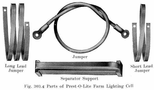
PREST-O-LITE FARM LIGHTING BATTERIES
|
|
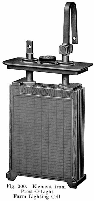
The Prest-O-Lite battery which is designed for use in connection with farm lighting plants is known as the FPL type. Cells of 7, 9, 11, 13 and 15 plates are made, the -number of plates being indicated by putting the figure in front of the type letters. A seven plate cell is thus designated as a 7 FPL cell, which has an 80 ampere hour capacity at the 8 hour continuous discharge rate. |
Specific Gravity of Electrolyte. The values of the specific gravity of Prest-O-Lite farm lighting batteries are as follows:
- Battery fully charged reads 1.250
- Battery three-fourths charged reads 1.230
- Battery one-half charged reads 1.215
- Battery one-fourth charged reads 1.200
- Battery discharged completely reads 1.180
These readings are to be taken with the electrolyte at a temperature of 80° Fahrenheit. Readings taken at other temperatures should be converted to 80°. To convert readings at a lower temperature to the values they would have at 80°, subtract one point for every two and one-half degrees temperature difference. For example, suppose a cell reads 1.225 gravity at 60°. To find what the gravity would be if the temperature of the electrolyte were 80° divide the difference between 80° and 60° by 2-1/2, or 80° minus 60° divided by 21/2 equals 8. The gravity at 80° would therefore be 1.225 minus .008, or 1.217, which is the value of specific gravity to use. If the specific gravity is read at a higher temperature than 80°, divide the difference between 80° and the temperature at which the gravity reading was taken by 21/2, and add the result to the actual gravity reading obtained. If, for example, the gravity were 1.225 at 100°, the gravity at 80° would be 1.225 plus .008, or 1.233.
This apparently works out to:
(gravity at temp) + (temp __ 80°)/2500 = (gravity at 80°)
or
(gravity at Temp-A) + (Temp-A __ Temp-B)/2500 = (gravity at Temp-B)
Charging Rates. The normal charging rate to be used in giving Prest-O-Lite batteries a regular charge or overcharge are as follows:
|
Battery |
Charging Rate |
|
5 F.P.L. |
5.0 amps. |
|
7 F.P.L. |
7.5 amps. |
|
9 F.P.L. |
10.0 amps. |
|
11 F.P.L |
12.5 amps. |
|
13 F.P.L. |
15.0 amps. |
|
15 F.P.L. |
17.5 amps, |
Rebuilding Prest-O-Lite Farm Lighting Batteries
Opening the Cell.1. Make sure that the cell is as fully charged as possible. Since it is not very convenient to charge a single cell, a good time to open a cell for cleaning and repairing is immediately after the battery has been given an overcharge. See page 455.
2. Disconnect the cell from the adjoining ones.
3. Heat a thin bladed putty knife and insert it 'under the edge of the lead-antimony cover to melt the sealing compound. Run the knife all round the cover, heating it again if it should become too cool to cut the compound readily.
4. Grasp the lead posts above the cover and lift up gradually. This will bring up the cover, plates, and separators.
5. Place the plates on a clean board for examination. Use the instructions given on pages 339 to 346. Do not keep the plates out of the electrolyte long enough to let them dry, and the negatives heat up. If you cannot examine the plates as soon as you have removed them immerse them in 1.250 acid contained in a lead or non-metallic vessel until you can examine them.
6. In renewing the electrolyte, pour in as much new 1.250 acid as there was old electrolyte in the jar. (It is assumed that the electrolyte was up to the lower ridge of the glass jar before the cell was opened.) The new electrolyte must not have a temperature above 100' when it is poured into the jar.
7. The separators can be pulled out easily when the plates are laid on their sides. All that is necessary is to remove the small rubber bridge at the bottom corners of the plates. The separators can then be pulled out. If the old separators are to be used again brush off any material that may be adhering to them, and keep them wet with 1.250 acid until they are replaced between the plates. Any separators that show cracks or holes, or that split while being replaced between the plates should be thrown away and new ones used.
8. It is not- necessary to remove the sediment from the bottom of the jar unless it is within one half inch of the bottom of the plates. If the sediment is to be removed, carefully pour off the clear electrolyte into a lead, hard rubber, or earthenware jar, if the electrolyte is to be used again.
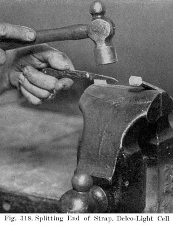
9. If one or two of the plates in either positive or negative groups need to be replaced it is best to burn a new plate to the strap without removing the peened cover. This is done by blocking under the row of -plate lugs with metal blocks after cutting off old plate and cleaning the surface of strap. Insert new plate, the lug of which has been cut about 1/4 inch short, to allow for new metal. Choosing small oblong iron blocks of suitable size, build a form about the plate lug which fits same well. Now with a torch and burning lead fuse the new plate onto the old strap. When cool remove and test joint by pulling and slightly twisting the plate at the same time.
Sometimes one group of a starting and lighting battery may be in sufficiently good condition to pay to combine it with a new group, but this condition will very rarely, if. ever, be met in farm lighting cell service. We advise the replacement of the complete cell element if either group is worn out, for the cost of repairs and of new group will probably not be warranted by the short additional life which the remaining old group will give.
10. Putting Repaired Cell Back into Service. After having finished all necessary cleaning, replacement, or repairs, remove all old sealing material, return the element with attached lead cover to the cell jar. It is not necessary to reseal the cover to the jars this sealing is essential only for insurance against breakage or leakage in shipment.
Add through the vent plug opening sufficient cool acid of 1.250 Sp. Gr. to reestablish the proper electrolyte level, which means that the electrolyte is brought up to the lower moulded glass ridge near the top of jar.
Connect the cell with any other repaired cells and charge at normal rate already indicated under "charging rates" until dell voltage reads 2.5 or above, at 80°. The positive to cadmium voltage should be at least 0.10 volts less than cell voltage itself. When this condition is obtained cell may be replaced in operating circuit with others and should give satisfactory service.
EXIDE FARM LIGHTING BATTERIES.
Exide Farm lighting Batteries are made with sealed glass jars, open glass jars, and sealed rubber jars, each of which will be described.
Batteries with Sealed Glass Jars.
Two types with sealed glass jars are made, these being the Delco Light Type, and the Exide type.1. Delco-Light Type. This type is shown in Fig. 294. The cell shown is a pilot cell, there being two of these in each battery as explained below.
These cells are made in two sizes, the KXG-7, 7 plate, 80 ampere hour cell, and the KXG-13, a 13 plate, 160 ampere hour cell. These cells are assembled into a 32 volt, 16 cell battery, or a 110 volt, 56 cell battery.
The plate groups are supported from the cover, the weight being carried by the wooden cover supports as shown in Fig. 294. The strap posts are threaded, and are clamped to the cover and supports by means of alloy nuts, just as is the case in Exide automobile batteries.
A hard rubber supporting rod or lock pin extending across the bottoms of the plates holds the separators in position and prevents the plates from flaring out at the bottom. A soft rubber bumper fastened on each end of the rod acts as a cushion to prevent jar breakage in shipping.
The hard rubber cover overlaps the flanged top of the jar, to which it is sealed with special compound.
Battery Gauges and Instruments for Testing.
Every set of Delco-Light batteries has either one or two cells equipped with a pilot ball. Such a cell is known as a PILOT CELL. Fig. 294.Pilot Cells are used to indicate to the USER the approximate state of charge or discharge of the battery.
The pilot ball is a battery gauge which is UP or DOWN, depending upon the state of charge of the battery.
Very high temperature affects the operation of the pilot ball. This accounts for-the fact that occasionally a battery will be charged and the pilot ball will be at the bottom of the pocket. A few hours later, after the electrolyte has cooled, the pilot ball will rise to the top.
We urge that the user be made to feel that the pilot ball is an excellent gauge and a good signal to watch in connection with the care and operation of his Delco-Light plant and battery. (Further mention will be made of the pilot ball in connection with the subject of proper operation.)
It is necessary that the maximum specific gravity of pilot cells be as near 1.220 as possible. Any great variation higher or lower will affect the operation of the pilot balls. Therefore, every effort should be made to adjust the maximum specific gravity of pilot cells to 1.220 when placed in service.
Batteries equipped with one pilot cell contain a white pilot ball which will be up when the specific gravity of the electrolyte is approximately 1.185. This ball will drop DOWN when the specific gravity falls a little below 1.185.
In other words, the pilot ball will float at a specific gravity of 1:185 or higher, and will sink at a specific gravity lower than 1.185.
Therefore, when the pilot ball is UP, the battery is more than half charged. When the pilot ball is DOWN, the battery is more than half discharged.
Batteries equipped with two pilot cells have one cell which contains a white ball and the other cell a white ball with a blue band.
The plain white ball will be UP when the specific gravity is approximately 1.175. The blue band ball will be UP when the specific gravity is approximately 1.205.
When both balls are UP, the battery is charged. When DOWN, the battery is discharged. The blue band ball will drop soon after the battery starts on discharge, or, in other words, when the specific gravity falls below 1.205. The white ball will remain UP until the specific gravity falls below 1.175.
|
|
The ampere-hour meter, Fig. 304, is an instrument for indicating to the user the state of charge of the battery at all times and serves to-stop the plant automatically so equipped, when the battery is charged. (Further mention will be made of the ampere hour meter on page 471.) |
The standard hydrometer for service men is known as the Type V-2B.A special type hydrometer showing three colored bands in' place of numbers has been designed for users.
The bands are red, green and black. When the hydrometer test shows the bottom of the red band in the electrolyte, the battery, whether in glass or rubber jar, is discharged. When the top of the green band is out of the electrolyte, the glass jar battery is charged. The top of the black band out of the electrolyte indicates the rubber jar battery is charged.
When and How to Charge Battery
Plants with Average Loads
Loads of legs than ten (10) amperes can be taken directly from the battery, until:1. The large hand on the ampere-hour meter reaches 12, or
2. Both pilot balls are down, or
3. Hydrometer test shows bottom of red band in the electrolyte.
If any or all of the three gauges listed above show the battery discharged, the plant should be started and operated continuously until the battery is charged, as indicated by:
1. Ampere-hour meter hand at FULL, or
2. Both pilot balls UP, or
3. Hydrometer test shows top of FULL band out of electrolyte.
(NOTE: Any one or all of the above three items may indicate battery charged. Meter hand at FULL would necessitate. both balls UP. If both balls are not up, set hand back and charge to bring them up; then set hand at FULL.)
Should the user be operating for two or three hours with a seven or eight-ampere load, it would be more efficient to run the plant to carry this load. This only applies for those cases where the battery is partly discharged.
Carry Heavy Loads Greater Than 10 Amperes.
If there is a constant load of 10 amperes or more, the plant should be started up when the heavy load comes on. When the heavy load is off, the plant may be stopped, but it would be entirely satisfactory to allow the plant to continue to run until "Charged," as indicated by:1. Ampere-hour meter hand reaches FULL, or
2. Both pilot balls are UP, or
3. Hydrometer test shows top of FULL band out of electrolyte.
In any case, plant should be run until battery is "Charged" at least once a week.
Always Start Charging When Battery Gauges Indicate Battery Discharged.
On ampere-hour meter plants, when the hand is at FULL, the plant cannot be operated on account of the ignition circuit being broken.
In such cases allow load to be taken from the battery until the hand travels back sufficiently to allow the plant to run.
Occasionally the plant and battery are used to carry continuous loads of from 10 to 15 amperes each night, with practically no day load. This condition necessitates running the plant to carry the load, but at the same time the battery is continually receiving from 1O to 15 amperes charge, with the result that the battery may receive too much charging. This would be indicated by the battery bubbling freely every time the plant is operated. To prevent this condition, the user should be instructed to carry the load off the battery frequently enough to prevent continual bubbling.
Where Small Load Is Used.
There are many installations where the battery capacity is sufficient to last several weeks. On installations of this kind it is advisable to charge the battery to FULL at least once a week.The dealer or service man should use his own judgment on the preceding instructions as to which is best suited for the different conditions encountered.
Regularly on the first of each month, regardless of whether or not the battery has been used, a special charge, called the Equalizing Charge, should be given. This charge should be given as follows: The battery should be charged until EACH cell is bubbling freely from top to bottom on surface of the outside negative plates and then the charge should be continued for TWO MORE HOURS.
The monthly equalizing charge is a NECESSARY precautionary measure to insure that the user will bring each cell in the battery up to maximum gravity at least once a month. It also provides a means on the ampere-hour meter plants to set the ampere-hour meter hand at FULL when the battery is FULL.
The users should be cautioned to inform the service man or dealer immediately if any cell fails to bubble at the end of an equalizing charge, when all others are bubbling freely. This will enable the service man to inspect such cells for trouble and remedy same before the trouble becomes serious. (See further information under inspection and repairs.)
Undercharging or injurious sulphation is the most common trouble encountered. Undercharging causes the plates to blister and bulge, and in place of good gray edges on the negative plates and good brown color edges on the positive plates, the edges will show a faded color, with very little brown color showing on the edges of the positive plates.Overcharging is not so evident on inspection, except that in such cases the active material from the positive plates, which is brown in color, will be thrown to the bottom as sediment more rapidly than the sediment would accumulate due to normal wear.
Heavy usage -on a battery will also cause considerable sediment in the bottom of the cells, so that it is necessary to investigate carefully whether it is overcharging or overwork. A few questions as to method of operation and load requirements will aid in deciding the cause of excessive sediment. (See When and How to Charge, page 468.)
Sediment Space Filled.
When the space below the plates is filled up with sediment and touching the plates, the cell becomes short-circuited and will deteriorate very rapidly. It will be noticed, however, that the sediment is heaped in the middle of the cell. If the cells are unbolted and unshaken, it will level the sediment and leave a space between the sediment and plates. It is very important that the sediment be shaken down before the cell becomes short-circuited. This will very often prolong the life of the battery a number of months. When the sediment space is completely filled, approximately all the active material will be out of the positive plates.A thorough study should be made as to the general condition of the battery and method of operation before forming an opinion or suggesting any change in method of operation.
On plants which have ampere-hour meters, the meter should be checked as to its speed on discharge, and also check position of the meter hand at the time of inspection, to see if it checks with the specific gravity and the pilot balls. (See Ampere Hour Meter, page 467.)It will generally be found that when a battery is sulphated, it is operating in very low specific gravity, or, in other words, the charges have not been carried far enough to drive all the acid out of the plates.
A battery that is not receiving quite enough charge may not as a whole become "sulphated," but several cells might become considerably weaker than the others and become "sulphated," causing trouble in these particular cells. Such cells will not bubble freely, or possibly not at all, when the other cells are bubbling freely. Therefore, a few questions to the user will generally help in locating the low cells.
Cells that are in trouble, or which soon will be, can very easily be picked out by making a few tests on the battery. Therefore, on all inspections, regardless of the age of a battery, it is suggested that the following tests be made: Take a specific gravity reading of all cells and note if there are any cells much lower than the others. Amy cells having a specific gravity of 30 points lower than the average will generally be found to be in trouble, unless these cells happen to be low from having had spillage in shipment, replaced with water. (This condition, however, should not exist in future installations if the spillage is properly taken care of, as has been explained on page 482.)
Voltage Readings
After taking a specific gravity reading, a voltage reading of each cell should be taken. Voltage readings taken on open circuit are of no value, so while taking these readings the battery should be on discharge, having at least a discharge of 15 amperes. A good way to get this discharge is to hold the starting switch in and set mixing valve lever at lean point or wide open.A low or defective cell will show a voltage reading .10 to .20 volts lower than the other cells on discharge, while a reversed cell will show a reading in the reversed direction when on discharge, especially on heavy discharge.
The voltage readings are a sure check if taken in connection with the specific gravity. When you have low specific gravity and low voltage on the same cells, it is a sure indication of low cells. These cells should be inspected for the probable cause of their being low. Shorting of the lugs at bottom of plates and moss bridging across at bottom of the elements, or possibly a split separator, will generally be the main trouble.
When any of these conditions exist, it is best to take the low" cells back to your shop for repairs.
When there is absolutely no indication why the cells are low, they can be cut out of the battery on discharge and put in on charge, until they come up.
The following is a good example of readings taken on a battery with a 10-ampere discharge and having four low cells, 4, 8, 11 and 16. The battery had been giving poor service, due to insufficient charging:
|
Cell No. |
Specific Gravity |
Volts |
|
1 |
1.200 |
1.98 |
|
2 |
1.180 |
1.95 |
|
3 |
1.205 |
1.98 |
|
4 |
1.150 |
1.75 |
|
5 |
1.190 |
1.95 |
|
6 |
1.195 |
1.98 |
|
7 |
1.200 |
1.98 |
|
8 |
1.130 |
1.70 |
|
9 |
1.200 |
1.95 |
|
10 |
1.205 |
1.98 |
|
11 |
1.100 |
1.40 |
|
12 |
1.190 |
1.95 |
|
13 |
1.180 |
1.95 |
|
14 |
1.195 |
1.98 |
|
15 |
1.190 |
1.95 |
|
16 |
0.000 |
zero or reversal |
The main thing to consider in checking voltage readings is the variation from the average. The average voltage readings will vary, depending on the state of charge of the battery when the readings are taken.
REPAIRS
To repair, the following equipment is necessary:
- 1. Portable lead burning outfit.
- 2. A suitable blow torch.
- 3. Standard sealing nut wrench.
- 4. File (shoemaker's rasp).
- 5. Pair of pliers.
- 6. Putty knife.
- 7. Pair of tin snips.
- 8. Wooden blocks to support elements while being worked upon.
- 9. Good supply of battery parts consisting of:
- KXG-13 Glass jars
- KXG-13 Pilot jars
- KXG-13 Positive groups
- KXG-13 Negative groups
- KXG-13 Round rods
- KXG-13 Vent plugs
- Sealing nuts
- Rubber gaskets
- Wood separators
- KXG-13 Rubber covers
- KXG-7 Round rods
- Lead pins
- Carboy electrolyte (including retainer).
- KXG-7 Pilot jars
- KXG-7 Glass jars
- KXG-7 Positive groups
- KXG-7 Negative groups
- Outside negative plates
- KXG-7 Rubber covers
- Emergency repair straps
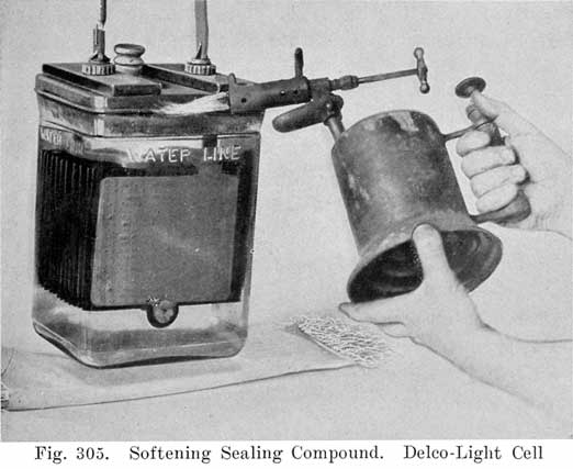
The glass jar battery covers are sealed to the jars by sealing compound, which may be softened very easily with a blow-torch.When a blow-torch or an open flame is used for softening the sealing compound, the vent plug MUST be removed before applying a flame. It is also important to blow into the vent after the plug has been removed in order to expel any gas that may have collected in the space above the electrolyte in the cell.
If the gas is held in place by leaving the vent plug in, it is apt to explode when an open flame or intense heat is applied to the cover.,
Removing covers may be greatly facilitated by suspending the cell by the terminals, as shown in Fig. 305. Care should be taken to make this suspension so that the bottom of the jar will not be more than two inches above the table. A pad of excelsior should be placed- under it to avoid breaking the glass jar when it drops.
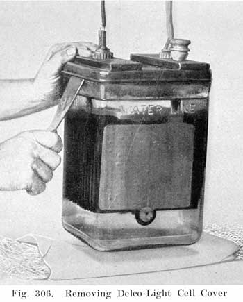
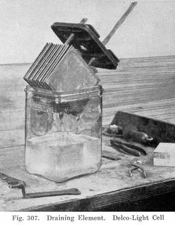
After the sealing compound has been sufficiently softened, the cover may be loosened by inserting a hot putty knife, as shown in Fig. 306, There is no danger of breaking the cover by this operation if the cover has been sufficiently warmed. After the jar of electrolyte has dropped, the element should be removed from the jar and carefully placed across the top of it, so that the solution upon the plates will drain back into the jar. (See Fig. 307.)
![]()
![]()
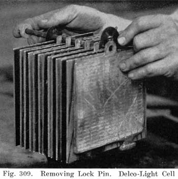
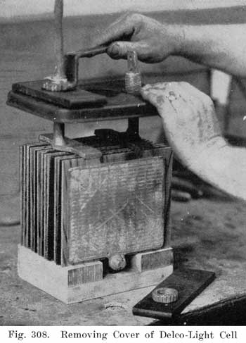
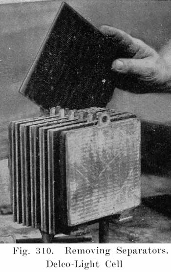
After element has drained, place on wooden blocks, as shown in Fig. 308, and remove cover. Clean the sealing compound. from the cover and jar immediately with a putty knife. Turn element upside down with posts through holes in bench and remove lead pin and rubber bumper and withdraw, lock pin. (Fig. 309.) The separators may then be withdrawn from the group. (Fig. 310.)
![]()
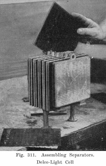
Place the positive and negative groups upside down with posts through holes in bench and slide in separators. The wood and rubber separators are inserted as follows: The rubber separator is placed against the grooved side of the wood separator. and the two are then slipped between the negative and positive plates with the rubber separator next to the positive plate. (See Fig. 311.)
Inserting Locking Pin
A rubber bumper is pinned on one -end of the lock pin by means of a lead pin, and the lock pin is then slipped into place with the lock pin insulating washer placed between the outside negative plates and the wood separators. (See Fig. 312.)A rubber bumper is then slipped over the other end of the lock pin and secured by a lead pin.
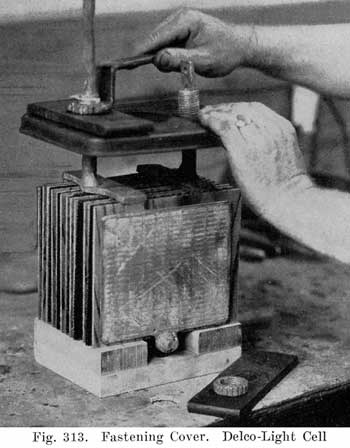
Place element on wooden blocks and fasten cover, as shown in Fig. 313.
![]()
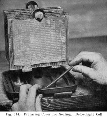
Sealing Covers
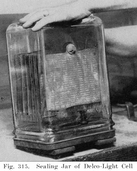
Be sure all old sealing compound and traces of electrolyte are removed from the cover. Heat sealing compound until it can be handled like putty, roll out into a strip about 1/2 inch in diameter, place strip of compound around inside edge of cover (Fig. 314) and heat to melting point with blow-torch. The top of jar should also be heated to insure a tight seal. Compound can be melted in a suitable vessel and a 1/2 inch strip poured around cover.When sealing compound and jar have been heated sufficiently, turn jar upside down (Fig. 315) and carefully place jar over element and press gently into compound. (Do not press hard.) Immediately place jar and element upright, and press cover firmly into place. (Press hard.) Finally, tighten sealing nuts. The cell is now ready for the electrolyte.
Filling Cell with Electrolyte
Repaired cells should be filled with electrolyte of 1.200 specific gravity, or with water, as the case may require.Standard Delco-Light electrolyte of 1.220 specific gravity may be purchased from the Delco Light distributor. The 1.220 electrolyte- should be reduced to 1.200 by adding a very small amount of distilled water. This should be thoroughly mixed by pouring the solution from one battery jar into another. The 1.200 specific gravity electrolyte may then be added to the newly assembled cell until flush with the water line.
The completed KXG-13 cell should be placed on a 12-ampere charge and kept on charge until maximum gravity has been reached. A KXG-7 cell should be charged at a 6-ampere rate.
Adjusting Gravity of Electrolyte
If the maximum gravity is above 1.220, draw off some of the electrolyte and refill to water line with distilled water. The charge should then be continued for at least one hour to thoroughly mix the electrolyte before taking another hydrometer reading. It may be necessary to repeat this operation.If the maximum gravity is below 1.220, pour off the electrolyte into a glass jar or a suitable receptacle, and then refill the cell with 1.220 electrolyte. Charge for one hour to thoroughly mix the solution before checking readings.
NOTE: Gravity readings in adjusting the electrolyte should always be taken in connection with thermometer readings, making necessary temperature corrections. This is particularly important in adjusting electrolyte in pilot cells.
HOW TO REPAIR DELCO-LIGHT CELLS
Treating Broken Cells
Whenever a shipment of batteries is received in which any of the jars have been broken, the first thing to do is to carefully remove the elements from the broken jars to prevent damage to the plates or separators. These elements should be placed in distilled water to prevent further drying. The plates will not be damaged in any way and can be restored to a healthy condition by charging in 1.200 specific gravity at a 12-ampere rate for the 13-plate cell or, 6-ampere rate for the 7-plate cell, until maximum gravity is reached. (See Charging and Adjustment of Electrolyte, explained on page 481.)
If the spillage is more than one inch below the water level, it should be replaced by electrolyte of 1.200 specific gravity and charged to maximum gravity.
Treating Badly Sulphated Cells That Have Been in Service
When cells are removed from an installation to make repairs, they are usually badly sulphated, which means that considerable acid is in the plates.In charging such cells, use distilled water in place of electrolyte, as this will allow the acid to come out of the plates more readily. The KXG-13 cells should be charged at about 12 amperes and the KXG-7 cells at 6 amperes. Cells badly sulphated when charged at the low rate will require from 50 to 100 hours to reach maximum gravity. Extreme cases will require even longer charging.
In case it is impossible to read the gravity after the cells have been on charge a sufficient length of time, pour out the solution and use 1.220 specific gravity.
The charge should then be continued further to insure that maximum gravity has been reached.
CAUTION: Should the temperature of the electrolyte approach 110° F., the charging rate should be reduced or the charge stopped until the cell has cooled.
A complete battery may be reversed if the battery is completely discharged and its voltage is not sufficient to overcome any residual magnetism the generator might have. Under such conditions the negative plates will begin to discolor brown and the positive turn gray. Such a case would be extremely rare.The remedy is to first completely discharge the cells to get rid of the charge in the wrong direction. Then short-circuit them. (Connect a wire across the terminals.) Then charge them in the right direction at a low rate. (12 amperes for a KXG-13 cell, or 6 amperes for a KXG-7 cell.) Charge until the specific gravity reaches a maximum. If the battery is operated reversed for any length of time, the negatives will throw off their active material and become useless.
A single cell may become reversed by gradually slipping behind the rest of the cells in a set, due to insufficient charging, until it becomes so low that it will reverse on each discharge. This condition cannot be corrected by giving the regular charge, but it will be necessary to give an equalizing charge, continuing the charge until the cell is in normal condition. (Be sure to make temperature corrections when taking hydrometer readings.) If the cell appears to require an excessive amount of charge to restore it to condition, it should be removed and taken to the repair shop for a separate charge.
If the cell has been allowed to operate in a reversed condition to such an extent that the entire material of the negative plates has turned brown, both positive and negative groups should be discarded.
Impurities, such as iron, salt (chlorine) or oil, may accidentally get into a cell, due to careless handling of distilled water.Iron is dissolved by sulphuric acid and the positive plates become affected, change color (dirty yellow) and wear rapidly. The cell becomes different from the rest in gravity, voltage and bubbling. The remedy is to discard the electrolyte as soon as possible, flush the plates and separators in several changes of water, thoroughly wash the jar, use new electrolyte and then proceed in same manner as explained for the treatment of badly sulphated cells, page 482.
Chlorine has an effect about as described for iron, and is evident by the odor of chlorine gas. The remedy is the same as for iron.
Oil in the electrolyte, if allowed to get into the pores of the plates, will fill them and lower the capacity very much. It affects negative plates much more than positives. Probably the only remedy in this case is new plates.
Impurities of any nature should be removed as quickly as possible.
Clearing High Resistance Short Circuits
A high resistance short is caused by the sediment falling from the plates and lodging between the positive and negative lugs. As a rule this condition will occur only when severe sulphation is present in the plates.A cell in this condition can be repaired by removing the element and clearing the short circuit. The wood separators should then be withdrawn and replaced by new ones. Lock pin insulating washers. should be installed land the element reassembled in the jar and charged to maximum gravity.
Short-circuited lugs are caused by excessive sulphation. The outside negative bulges and the bottom lug bends over and touches the adjacent positive lug. This can be remedied by removing both outside negative plates and burning on new plates which have already been charged and inserting lock pin insulating washers.
Putting Repaired Cells Back in Service
When placing a new or repaired cell in a battery which is in service, connect in the cell at the beginning of a charge. This will insure that the new or repaired cell is started off in good condition, because this charge is of the nature of an initial charge to these cells.
Charging Outside Negative Plates
Individual negative plates are always received dry, which makes it necessary to charge them before using. The best way to charge such plates is as follows: Set up 7 loose negative plates in a KXG-13 jar together with a good positive group, using KXG separators to prevent the plates touching. Then stretch a piece of wire solder across the lugs at the top of the negative plates and solder the wire to the plates. Fig. 316. The jar may then be filled with 1200 specific gravity and the plates charged at a 12-ampere rate until maximum gravity is obtained. Never use negative plates unless they have been treated as described above. After the charge is completed, the negative plates may be placed in distilled water and kept until ready for use. Always be sure to give a charge to maximum gravity after burning on new negative plates to an element.
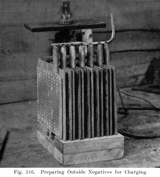
After badly sulphated cells are recharged, it is sometimes advisable to remove the elements and, press the negative plates, as explained on page 351. Care should be taken to prevent the negative plates from drying out while making repairs, in order to avoid the long charge necessary for dried negative plates.The battery should be charged to maximum gravity before attempting to press the plates.
It is not necessary and will do no good to press the positive plates.
In some cases the active material may be nearly all out of the outside negative plates and the inside negatives may be in good condition, in which case new charged plates should be burned on. (Fig. 322.)
When it has been necessary to replace cells which have been in service, the elements can very often be saved and assembled again and used as replacement cells in batteries which are several years old. In no case should the cells be used as new cells.The positive plates may be allowed to dry out, but the negatives should be kept in distilled water and not allowed to dry out in the least. They should not be kept this way indefinitely, but should be assembled and charged as soon as possible.
Do not attempt to repair groups or plates which have lost as much as half of the active material in wear, or which have the active material disintegrated and falling out. Such plates should not be used. This does not apply to small bits of active material knocked out mechanically and amounting to an extremely small percentage of the whole. Abnormal color indicates possible impurity, and such plates should be washed and used with caution. Badly cracked or broken plates should be replaced with new plates or plates from other groups.
Before new negative plates are used they should be fully charged. (See Charging Negative Plates, page 484.)
Always use new wood separators when assembling repaired cells.
When cells have been operated reversed in polarity to such an extent that the active material of the negative plates has turned brown, both positive and negative groups may have to be replaced.
The portable carbon burning outfit used for battery repairs is operated from the battery itself, making it possible to make repairs at the user's residence without using a gas flame.
This outfit can be secured from the Delco-Light Company, Dayton, Ohio, and consists of a carbon holder with cable, clamp, and one-fourth inch carbon rods. Six cells are usually required to properly heat the carbon. If it is completely discharged an outside source must be used. For this purpose a six-volt automobile battery is suitable, or a tray of demonstrating batteries, one terminal being connected to the connection to be burned, the other to the cable of the burning tool. A little experience will. soon demonstrate the number of cells necessary to give a satisfactory heat. The cable is connected by means of the clamp to a cell in the battery, the required number of cells away from the joint to be burned. Care should be taken that contact is made by the clamp, the lead being scraped clean before the connection is made. The carbon should be sharpened to a long point like a lead pencil and should project not more than 2 inches from the holder. (Fig. 317.)
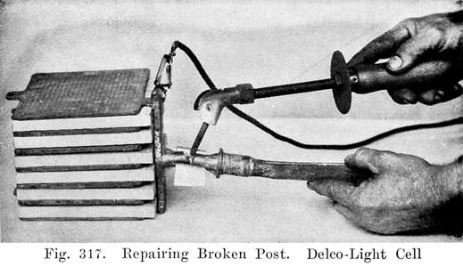
After being used a short time, the carbon will not heat properly, due to a film of scale formed on the surface. This should be cleaned off with a file.In case of lead burning, additional lead to make a flush joint should not be added until the metal of the pieces to be joined has melted. The carbon should be moved around to insure a solid joint at all points.
In case a post is broken off under the cover, proceed as follows: To make repairs take an old group and cut off the post about one-half way down. Saw off the post to be repaired to such a length that when the new post is burned on the length of the post will be approximately the same length as the original post.
Make a half circle mould out of a piece of tin or galvanized iron, as shown in Fig. 317. Burn solid the side of the post facing up, file it around and then turn the group over, place the form on the burned side and proceed to complete the burning operation.
Caution:1. Always use clean lead.
2. Do not clean the lead and let it stand for any length of time before starting to burn. If it is allowed to stand it will oxidize and prevent a good burning operation.
3. Burn with an are and not with a red hot carbon.
|
|
Place the strap to be burned in a vise and split the end through the center and then bend the two halves over to form a foot, as shown in Fig. 318. Make a mould out of a piece of tin or galvanized iron and place this mould around the post to which this strap is to be burned. (Fig. 319.) Then proceed to burn the post and strap together. |
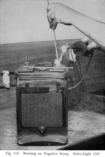
![]()
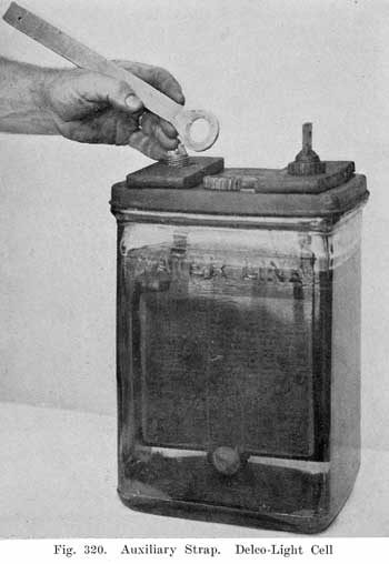
How to Eliminate Burning on Straps by Use of an Auxiliary Strap
A very good way to repair broken straps without the burning operation is to use the auxiliary strap shown in Fig. 320. This strap is slipped over the post of the terminal or strap which is broken and the sealing nut is then clamped down on the strap, as shown in Fig. 321. These straps may be obtained from the Delco-Light Distributors or from the Delco-Light factory at Dayton, Ohio.
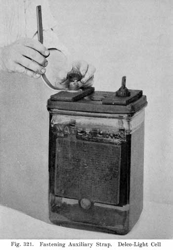
![]()
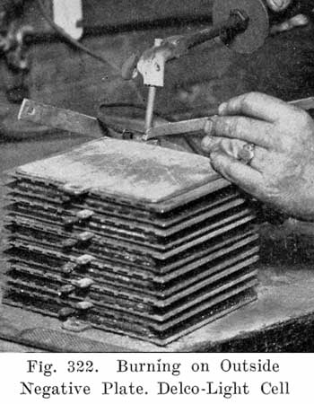
When it is necessary to burn on new plates, carefully clean with a file the lead on both the plate and the common strap to which all plates of the group are attached. Block up the plate with thin boards or wood separators until it is spaced the proper distance from the adjacent plate. Care should be taken to see that the side and bottom edge of the plate to be burned on is in line with the other plates of the group. Proceed to burn on the plate by drawing a small blaze or are and do not attempt to burn with just a glowing carbon. (Fig. 322.)If only a glowing carbon is used the result will be a smeary mass and in the majority of cases will not hold, due to the fact that it is not welded but simply attached in one or two points.
The principle of lead burning is to weld or burn two parts into one solid mass and not merely attach one to the other.
Keeping Wood Separators In Stock
No wood separators should be used except those furnished by the Delco-Light Company. These should be kept in distilled water, to which has been added 1.220 electrolyte in the proportion of one part to ten parts of water. It is advisable whenever possible to use new separators when making repairs on a cell. Separators which have been in service are liable to be damaged by handling.
Freezing Temperature of Electrolyte
The freezing temperatures of electrolyte in the Delco-Light batteries depends upon the specific gravity of the battery. The Delco-Light battery fully charged, with a specific gravity of 1.220, should not freeze above a temperature of 30 degrees below zero. Since, however, the freezing point rises very rapidly with a decrease in specific gravity, special care should be taken to keep batteries charged when temperatures below zero are encountered. The following table shows freezing temperatures of several different gravities of electrolyte.
|
Specific Gravity |
Freezing Point |
|
1.100 |
19° F. above zero. |
|
1.150 |
5° F. above zero. |
|
1.175 |
6° F. below zero. |
|
1.200 |
16° F. below zero. |
|
1.220 |
31° F. below zero. |
At the temperature given, the electrolyte does not freeze solid, but forms a slushy mass of crystals, which does not always result in jar breakage.
Frequently a Dealer or Distributor will have' several sets of new batteries in stock for five or six months. In this case, the cells should be given a freshening charge before putting into service. This charge should consist of charging the cells to maximum gravity.Cells received broken in transit or cells sent in for repairs should be repaired and charged as soon as possible and put into service immediately. This eliminates the possibility of the cells standing idle over a long period in which they would need a freshening charge before they could be used.
However, if such cells must be kept in stock, they can be maintained in a healthy condition by keeping on charge at a one fifth ampere rate for 13-plate cells and one-tenth ampere rate for 7-plate cells.
Taking Batteries Out of Commission
If a battery is not to be used at all for a period not longer than about 9 months, it can be left idle if it is first treated as follows: Add sufficient water to bring the electrolyte up to the water line in all cells and then give an equalizing charge, continuing the charge until the specific gravity of each cell is at a maximum, five consecutive hourly readings showing no rise in gravity. As soon as this charge is completed, take out the battery fuse and open up one or two of the connections between cells so that no current can be taken from the battery. Have vent plugs in place to minimize evaporation.If the battery is to be taken out of commission for a longer time than 9 months, the battery should be fully charged as above and the electrolyte poured off into suitable glass or porcelain receptacles. The plates should immediately be covered with water for a few hours to prevent the negatives heating, after which the separators should be removed, the water poured out of the jars, and the positive and negative groups placed back in the jar for storage. Examine the separators. If they are cracked or split they should be thrown away. If in good condition they should be stored for further use in a non-metallic receptacle and covered with water, to which has been added electrolyte of 1.220 specific gravity, in the proportion of one part electrolyte to ten of water by volume.
Putting Batteries Into Commission After Being Out of Service
When putting batteries into commission again, if the electrolyte has not been withdrawn, all that is necessary is to add water to the cells if needed, replace connections, and give an equalizing charge.If the electrolyte has been withdrawn and battery disassembled, it should be reassembled, taking care not to use cracked, split or dried-out separators, and then the cells should be filled with the old electrolyte. which' has been saved, provided no impurity has entered the electrolyte. After filling, allow the battery to stand for 12 hours and then charge, using 6 amperes for KXG-7 size and 12 amperes for the KXG-13 size. Charge at this rate until all cells start gassing freely or temperature rises to 110° F. Then reduce the charging rate one-half, and continue at this rate until the specific gravity is at a maximum, five consecutive hourly readings showing no rise in gravity. At least 40 hours will be required for this charge. To obtain these low rates with the Delco-Light plant, lights or other current-consuming devices must be turned on while charging.
General Complaints from Users and How to Handle Them.
1. Pilot balls do not come up.
This condition may be caused by
- (a) Battery discharged.
- (b) Weak electrolyte caused by spillage in shipment.
- (c) Defective ball.
Question the user to determine whether the ball will not come up if the pilot cell is bubbling freely. Weak electrolyte or a defective ball will require a service trip to determine the one which is responsible for the ball not rising. (See page 470.)
2. Lights dim-must charge daily.
This condition may be caused by
- (a) Discharged battery.
- (b) Loose dirty connections in battery or line.
- (c) Low cells in battery.
The user should be questioned to determine whether the battery is being charged sufficiently. In case the user is positive the battery is charged, the next probable trouble would be that there were some loose or dirty connections in either plant or battery. Have the user check for loose connections. Should it be necessary to make an inspection trip, instruct the user to give battery an equalizing charge so the battery will be fully charged when the inspection is made.
Low cells can be checked by asking the user if all of the cells bubble freely when equalizing charge is given. In case user claims several cells fail to bubble, an inspection trip would be necessary to determine the trouble. (See page 470.)
3. Cells bubbling when on discharge.
This complaint would indicate a reversed cell. (See page 483.)
4. Cells overflowing on charge.
This would mean that the cells were filled too high above water lines.
5. Engine cranks slowly but does not fire.
This would indicate over-discharged battery. Explain to user how to start plant under this condition.
6. Plant will not crank.
This might be caused by
- (a) Blown battery fuse.
- (b) Battery over-discharged.
- (c) Loose or broken connection on battery or switchboard.
OTHER EXIDE FARM LIGHTING BATTERIES
The Exide type is shown in Figure 296. The plates are held in position both by the cover and by soft rubber support pieces in the bottom of the jar. The support pieces are provided with holes in which projections on the bottom of the plates are inserted. The cover is of heavy moulded glass. The separators are of grooved wood in combination with a slotted rubber sheet (Fig. 297). The strap posts are threaded and are clamped to the cover by means of alloy nuts. The cover overlaps the top of the jar to which it is sealed with sealing compound. The method of sealing and unsealing is practically the same as in the Exide Delco-Light Type."
Batteries with Open Glass Jars
Batteries with open glass jars, in addition to the conducting lug, have two hanging lugs for each plate. The plates are hung from the jar walls by these hanging lugs, as shown in Figs. 323 and 324. The plate straps, instead of being horizontal are vertical and provided with a tail so that adjacent cells may be bolted together by bolt connectors through the end of the tail.1. The Exide Cell is shown in Fig. 324. It has a grooved wood separator between each positive and negative plate. The separators are kept from floating up by a glass "hold-down" laid across the top. The separators are provided at the top with a pin which rests on the adjoining plates. The pins together with the plate glass hold-downs keep the separators in Position.
To remove an element it is simply necessary to unbolt the connectors, remove the glass cover and hold-down and lift wit the element.
2. The Chloride Accumulator cell is shown in Fig. 323. It differs from the Exide only in type of plates and separators. The positive plates are known as Manchester positives and have the active material in the form of corrugated buttons which are held in a thick grid, as shown in Fig. 325. The buttons are brown in color, the same as all positive active material.
The separators, instead of being grooved wood, am each a sheet of wood with six dowels pinned to it.
The element is removed the same as in the Exide type.
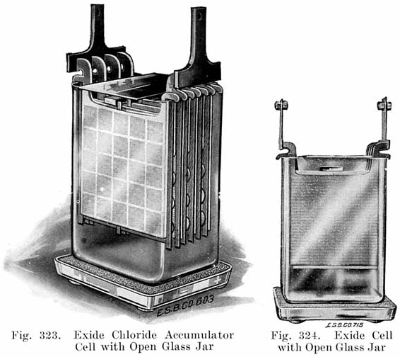
Batteries with Sealed Rubber Jars
1. The Exide cell is shown in Fig. 326. It is assembled similar to Exide starting and lighting batteries, except that the plates are considerably thicker, wood and rubber separators are used, and the terminal posts are shaped to provide for bolted instead of burned-on connection. The method of sealing and unsealing the cells is the same as in Exide starting and lighting batteries.All instructions already given for glass for cells apply to rubber jar cells except for a few differences in assembling and disassembling.
Care should be taken to keep the water level at least 1/2 inch above plates at all times as the evaporation is very rapid in rubber jar cells.
The temperature should be watched on charging to prevent overheating. Never allow temperature to go above 110° F.
Unlike the glass jar cells the sediment space in the rubber jar is not sufficient to take care of all the active material in the positive plates. On repairs, therefore, always clean out the sediment and prevent premature short circuits.
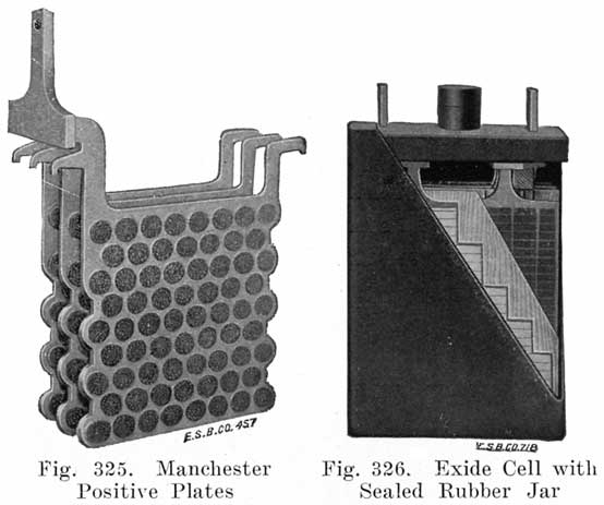
WESTINGHOUSE FARM LIGHTING BATTERIES
Jars. Westinghouse Farm Lighting Battery jars are made of glass, with a 5/16 inch wall. The jars are pressed with the supporting ribs for the elements an integral part from a mass of molten glass. A heavy flange is pressed around the upper edge to strengthen the jar.Top Construction. A sealed-in cover is used similar to that used in starting and lighting batteries. The opening around the post hole is sealed with compound.
Plates. Pasted plates are used. The positives are 1/4 inch thick, and the negatives 3/16 inch. Posts are 13/16 inch in diameter.
Separators. A combination of wood and perforated rubber sheets is used.
Opening and Setting-Up Westinghouse Farm Lighting Batteries
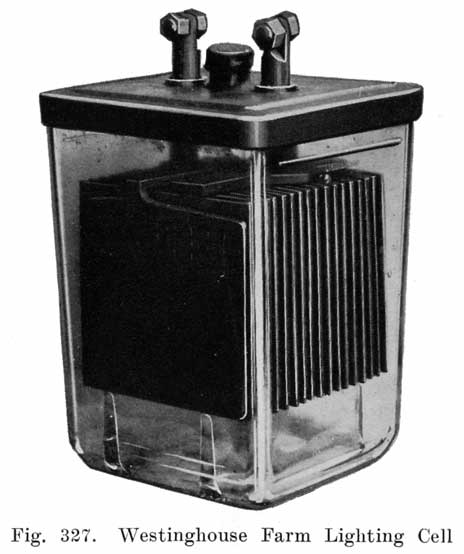
It is preferable that the temperature never exceed 100 deg. Fahrenheit nor fall below 10 deg. in the place where the battery is set up. If the temperature is liable to drop below 10 degrees the battery should be kept in a fully charged condition.1. Remove all excelsior and the other packing material from the top of the cells. Take cells out carefully and set on the floor. Do not drop or handle roughly. Be sure to remove the lead top connectors from each compartment.
2. Cells should be placed 1/4 inch apart. Also, cells should be placed alternately so that positive post of one cell is adjacent to negative post of the next cell. Positive post has "V" shape shoulder and the negative post has a square shoulder.
3. Grease all posts, straps and nuts with vaseline.
4. Connect positive posts of each cell to negative post of adjacent cell, using top connectors furnished. Top connectors are made so as to fit when connection is made between positive post of one cell and negative post of next cell. Use long connector between end cells of upper and lower shelves.
5. With all connections between cells in position, join the remaining positive post with a connection marked "Positive" leading from the electric generator. Do likewise with the remaining negative post.
6. If liquid level in any cell is 1 inch or more below the "Liquid Line" on side of glass jar, some liquid has been spilled and must be replaced. This should be done by an experienced person.
7. Immediately after installation operate electric generator and charge battery until gas bubbles rise freely through the liquid in all cells. A reading with the hydrometer syringe which is furnished with the battery should be taken, When the hydrometer float reads between 1.240 and 1.250, the battery is fully charged.
8. The time required to complete the charging operation mentioned above may vary from one to several hours, depending upon the length of time the battery has been in transit. During the charge the temperature of the cells should not be permitted to rise above 110 deg. Fahrenheit. If this condition occurs discontinue the charge or decrease the charge rate until cells have cooled off.
9. When charge is complete replace vent plugs.
The Relation Between Various Sizes of Westinghouse Farm Light Batteries and Work to be Done
The size of the battery furnished with complete farm lighting units vary greatly. Sometimes the battery size is varied with the size of the engine and generator, while again the same size of battery may be used for several sizes of engines and generators. In making replacements, while it is always necessary to retain the same number of cells, it is not necessary to retain the same size of cells.Usually increasing the cell size increases the convenience to the owner and prolongs the life of the battery to an amount which warrants the higher cost.
With a larger battery, danger of injury through overcharging is lessened, the load on the battery is more easily carried and the engine and generator operate less frequently.
In order to give an idea of various battery capacities, below is a table showing the number of 32 volt, 25-watt lamps which may be lighted for various lengths of time from sixteen cells. The number of hours shows the length of time that the lamps will operate.
Table A
|
Type |
3 Hours |
5 Hours |
8 Hours |
|
G-7 |
22 Lamps |
14 Lamps |
10 Lamps |
|
G-9 |
28 Lamps |
19 Lamps |
13 Lamps |
|
G-11 |
32 Lamps |
24 Lamps |
15 Lamps |
|
G-13 |
41 Lamps |
28 Lamps |
19 Lamps |
|
G-15 |
47 Lamps |
33 Lamps |
22 Lamps |
|
G-17 |
54 Lamps |
38 Lamps |
25 Lamps |
Note:--Based on 32-Volt 25-Watt Lamps.
For example- The table shows opposite G-7 that, with the battery fully charged, twenty-two lamps may be lighted for three hours, fourteen lamps for five hours and ten lamps for eight hours, by a sixteen cell G-7 battery, without operating the engine and generator.Motors for operating various household and farm appliances are usually rated either in horsepower or watts. The following table will give a comparison between horse-power and watts as well as the number of 25-watt lamps to which these different sizes of motors and appliances correspond.
Table B
|
H. P. of Motor |
No. of Watts |
Corresponding Corresponding No. of 25-Watt Lamps |
|
1/8 |
93 |
4 |
|
1/4 |
185 |
7 |
|
1/2 |
373 |
15 |
|
3/4 |
559 |
22 |
|
1 H.P. |
746 |
30 |
From table B it will be seen, for example, that a one horsepower motor draws from the battery 373 watts or the same power as do fifteen 25-watt lamps. Then referring to table A, it will be found that a G-11 battery could operate 15 lamps or this motor alone for 8 hours.Due to the fact that a motor or electric appliance may become overloaded and therefore actually use many more watts than the name plate indicates, it is not advisable to operate any motor of over 1/4 H. P. or even an appliance of over 186 watts on the G-13 or smaller sizes unless the engine and generator are running.
It is safe, however, to operate motors or other appliances up to 375 watts on the G-15 or G-17 batteries without operating the engine and generator.
WILLARD FARM LIGHTING BATTERIES
|
|
The Willard Storage Battery Co. manufactures farm lighting batteries which use sealed glass jars, or sealed rubber jars. Those using the sealed glass jars include types PH and PA. The sealed rubber jar batteries include types EM, EEW, IPR, SMW, and SEW. Both types of batteries are shipped fully charged and filled with electrolyte, and also dry, without electrolyte. The following instructions cover the installation and preparation for service of these batteries. |
Unpacking
Remove the boards from the tops of the shipping crates and the excelsior which is above the cells.To straighten the long top connector, grasp the strap firmly with the left hand close to the pillar post and raise the outer end of the strap until it is in an upright position. Do not make a short bend near the pillar post. Lift the cells from the case by grasping the glass jars. Do not attempt to lift them by means of the top connectors.
Clean the outside of the cells by wiping with a damp cloth.
Inspection of Cells.
Inspect each cell to see if the level of the electrolyte is at the proper height. This is indicated on the jar by a line marked LIQUID LINE.If the electrolyte is simply a little low and there is no evidence of any having been spilled (examine packing material for discoloration) add distilled or clean rain water to bring the level to the proper height.
If the liquid does not cover the plates and the packing material is discolored, it indicates that some or all of the electrolyte has been lost from the cell either on account of a cracked jar or overturning of the battery.
If only a small quantity of electrolyte is lost through spilling, the cell should be filled to the proper height with electrolyte of the same specific gravity as in the other cells. This cell should then be charged until the gravity has ceased rising. If all the electrolyte is lost write to the Willard Storage Battery Co., Cleveland, Ohio, for instructions.
Connecting the Cells
Each cell of the type PH battery is a complete unit, sealed in a glass jar. The cells are to be placed side by side on the battery rack so that the positive terminal of one cell (long connecting strap) can be connected to the negative terminal (short strap) of the adjacent cell.
Join the positive terminal of one cell to the negative terminal of the adjacent cell and continue this procedure until all the cells are connected together. This will leave one positive and one negative terminal of the battery to be connected respectively to the positive and negative wires from the switchboard. The bend in the top connector should be made about one inch above the pillar post to eliminate the danger of breakage at the post.
In tightening the bolts do not use excessive force, as there is liability of stripping the threads.
Give the battery a freshening charge before it is put in service. Type PH cells have a gravity of 1.250 when fully charged, and 1.185 when discharged.
Willard Glass Jar Batteries Shipped "Knock-Down."
Each sixteen cell set of Batteries consists of:
- 16 Glass Jars.
- 16 Positive Groups.
- 16 Negative Groups.
- 16 Covers.
- 16 Vent Plugs.
- 32 Lead Collars.
- 32 Lead Keys.
- 32 Soft Rubber Washers.
- 32 Hard Rubber Rods.
- 64 Hard Rubber Nuts.
- 18 Bolt Connectors.
- Wood Insulators (the quantity depends upon the size of the cells).
- Sealing Compound.
- Hydrometer.
- Instruction Books.
- Electrolyte is not supplied with batteries shipped in a knockdown condition.
- Examine all packing material carefully and check the parts with the above list.
Cleaning the Glass Jars
Wash the glass jars and wipe them dry.
Preparing the Covers
Wash the covers and scrub around the under edge to remove all dust. After they are thoroughly dry place them upside down on a bench.Melt the sealing compound and pour it around the outer edge to make a fillet in the groove.
Assembling the Element and Separators
Place the plates of a positive group between the plates of a negative group and lay the element thus formed on its edge, as shown in Fig. 329.
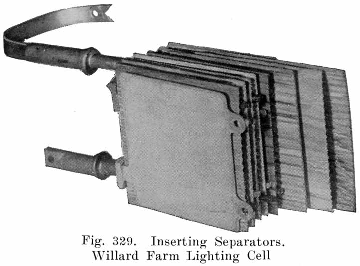
|
|
Next insert a wood separator between each of the positive and negative plates. |
Sealing Element Assembly in Jar
|
|
Turn the element upside down and place over a block of wood so that the weight is supported by the cover. (See Fig. 332.) |
Filling with Electrolyte
Fill the cells with 1.260 specific gravity electrolyte at 70° F. to the LIQUID LINE marked on the glass jars. (About I inch above the top edge of separators.) Allow the cells to stand 12 hours, and if the level of the electrolyte has lowered, add sufficient electrolyte to bring it to the proper height.
Initial Charge
Connect the positive terminal (long strap) of one cell to the negative terminal (short strap) of the adjacent cell and continue this procedure until all the cells are connected together. This will leave one positive and one negative terminal to be connected respectively to the positive and negative wires from the charging source.The bends in the top terminal connectors should be made about one inch above the pillar posts to eliminate the danger of breakage at the post.
In tightening the bolts, do not use excessive force, as there is liability of stripping the threads.
After the cells have stood for 12 hours with electrolyte in the jars, they should be put on charge at the following rates:
|
Type |
Amperes |
|
PH-7 |
4 |
|
PH-9 |
5 |
|
PH-11 |
6-1/4 |
|
PH-13 |
7-1/2 |
|
PH-15 |
9 |
|
PH-17 |
10 |
They should be left on charge continuously until the specific gravity of the electrolyte reaches a maximum and remains constant for six hours. At this point, each cell should be gassing freely and the voltage should read about 2.45 volts per cell, with the above current flowing.Under normal conditions it will require approximately 80 hours to complete the initial charge. The final gravity will be approximately 1.250. If the gravity is- above this value, remove a little electrolyte and add the same amount of distilled water.
If the gravity is too low, remove a little of the electrolyte and add the same amount of 1.400 specific gravity acid and leave on charge as before.
After either water or acid has been added, charge the cells three hours longer in order to thoroughly mix the solution, and if at the end of that time the gravity is between 1.245 and 1.255, the cells are ready for service.
It is very important that the initial charge be continued until the specific gravity reaches a maximum value, regardless of the length of time required. The battery must not be discharged until the initial charge has been completed.
If it is impossible to charge the battery continuously, the charge can be stopped over night, but must be resumed the next day.
It is preferable to charge the battery at the ampere rate given above, but if this cannot be done, the temperature must be carefully watched so that it does not exceed 110° F.
Wilard Rubber Jar Batteries Shipped Completely Charged and Filled with Electrolyte
Immediately upon receipt of battery, remove the soft rubber nipples and unscrew the vent plugs.The soft rubber nipples are to be discarded, as they are used only for protection during shipment. Inspect each cell to see whether the electrolyte is at the proper height.
If the electrolyte is simply a little low and there is no evidence of any having been spilled (examine packing material for discoloration), add distilled water to bring the level to the proper height.
If electrolyte does not cover the plates and the packing material is discolored, it indicates that some or all of the electrolyte has been lost from the cell, either on account of cracked jar or overturning of the battery.
If only a small quantity of electrolyte is lost through spilling, the cell should be filled to the proper height with electrolyte of the same specific gravity as in the other cells. This cell should then be charged until the gravity has ceased rising, If all the electrolyte is lost, write to the Willard Storage Battery Co., Cleveland, Ohio, for instructions.
Place batteries on rack and connect the positive terminal of one crate to the negative terminal of the next crate, using the jumpers furnished.
The main battery wires from the switch board should be soldered to the pigtail terminals, which can *then be bolted to the battery terminals. Be sure to have the positive and negative battery terminals -connected respectively to the positive and negative generator terminals of switchboard.
Before using the battery, it should be given a freshening charge at the -rate given on page 510.
The specific gravity of the rubber jar batteries is 1.285-1.300 when fully charged, and 1.160 when discharged.
Willard Rubber Jar Batteries Shipped Dry (Export Batteries)
Batteries which have been prepared for export must be given the following treatment:Upon receipt of battery by customer, the special soft rubber nipples, used on the batteries for shipping purposes only, should be removed and discarded.
Types SMW and SEW batteries should at once be filled to bottom of vent hole with 1.285 specific gravity electrolyte at 70° F.
In mixing electrolyte, the acid should be poured into the water and allowed to cool below 90° F. before being put into the cells. If electrolyte is shipped with the battery, it is of the proper gravity to put into the cells.
Immediately after the batteries are filled with electrolyte, they must be placed on charge at one half the normal charging rate given on page 510, and should be left on charge continuously until the specific gravity of the electrolyte stops rising. At this point, each cell should be gassing freely and the voltage should read at least 2.40 volts per cell with one-half the normal charging current flowing.
If during the charge the temperature of the electrolyte in any one cell exceeds 105° F., the current must be reduced until the temperature is below 90° F. This will necessitate a longer time to complete the charge, but must be strictly adhered to.
Under normal conditions it will require approximately 80 hours to complete the initial charge. The final gravity of the types SMW and SEW will be approximately 1.285. If the gravity is above this value, remove a little electrolyte and add same amount of distilled water while the battery is left charging (in order to thoroughly mix the solution), and after three hours, if the electrolyte is within the limits, the cell is ready for service. If the specific gravity is below these values, remove a little electrolyte and add same amount of 1.400 specific gravity electrolyte. Leave on charge as before. The acid should be poured into the water and allowed to cool below 90° P. before being used. The batteries are then ready for service.
Installing Counter Electromotive Force Cells
Counter EMF cells, if used with a battery, are installed in the same manner as regular cells. They are connected positive to negative, the same as regular cells, but the negative terminal of the CEMF group is to be connected to the negative terminal of the regular cell group. The positive terminal of the counter CEMF group is then to be connected to the switchboard.
Table of Willard Farm Lighting Batteries
|
(Omitted 4 charts showing charge and discharge rates for different types of batteries, and "Lineal Feet Rack Space Required for...") |
|
|
|
| |||||||||